Plasma generating device

A generating device and plasma technology, applied in the direction of plasma, separation method, dispersed particle separation, etc., can solve the problems of large power consumption and high cost, and achieve the effect of reducing energy consumption, low operating cost, and low energy consumption

Inactive Publication Date: 2010-06-23
赵岳虎 +4
View PDF0 Cites 11 Cited by
  • Summary
  • Abstract
  • Description
  • Claims
  • Application Information

AI Technical Summary

Problems solved by technology

However, activated carbon, photocatalysts, and ultraviolet lamps are all consumables, and the co

Method used


Image

  • Plasma generating device
  • Plasma generating device
  • Plasma generating device

Examples


Embodiment 1

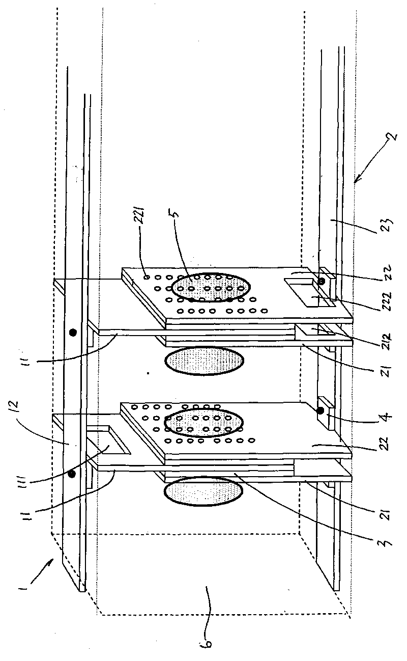
[0044] see figure 1As shown in the structural diagram of Embodiment 1 of the present invention, a plasma generating device is used for gas treatment. The plasma generating device is arranged in a gas flow channel 6 that is closed around and open at both ends. The first electrode 1 is formed by the first A common electrode 12 is connected with two or more first electrode units arranged side by side (only two are shown in the figure), and the first electrode unit is composed of a metal sheet 11;

[0045] The second electrode 2 is composed of a second common electrode 23 and two or more second electrode units arranged side by side (only two are shown in the figure), and each electrode unit is composed of two metal sheets 21 , 22 constitute;

[0046] A metal sheet 11 of each first electrode unit overlaps two metal sheets 21, 22 of the second electrode unit alternately on both sides, and the first electrode 1 and the second electrode 2 are separated by an insulating layer 3 at the...

Embodiment 2

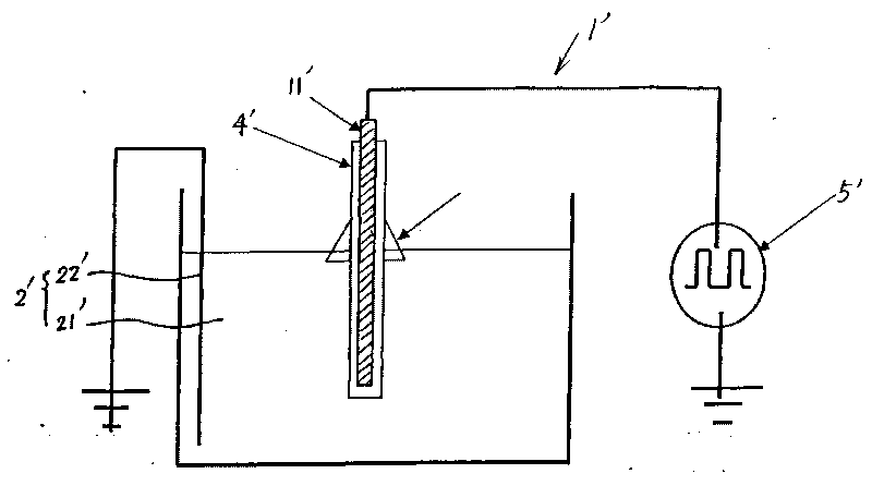
[0054] see figure 2 As shown in the schematic diagram of the structure of Embodiment 2 of the present invention, a new type of plasma generating device includes two electrodes, and the first electrode 1' is an electrode unit composed of an insulating layer 3' coated with a metal rod 11', which is insulated Layer 3' is an insulating material (glass) cladding layer, and a liquid (water) 21' inserted with a grounding conductor 22' is used as a second electrode 2', wherein the lower part of the first electrode 1' is inserted into the electrode 2' And the insertion part is not less than 2mm, so that the upper part of the first electrode 1 is exposed to the air, the first electrode 1' and the second electrode 2' are connected and separated by an insulating layer 3', and the wall thickness of the insulating layer is not more than 0.5 mm, the covering area of ​​the insulating layer 3' is larger than the entire insertion part of the first electrode 1';

[0055] Under normal temperatu...

Embodiment 3

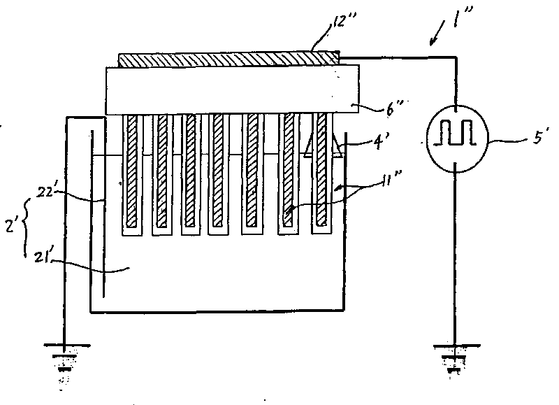
[0059] see image 3 As shown in the schematic diagram of the structure of Embodiment 3 of the present invention, the first electrode 1" is composed of a common electrode 12" and seven electrode units 11". The structure of the electrode units 11" is the same as that of Embodiment 2, except that the first The electrode 1' is composed of seven first electrode units 1" connected in parallel on the electrode support 6".


PUM


Abstract

The invention relates to a plasma generating device which can generate oxidant containing hydroxyl radicals and carry out oxidation treatment on gas liquid. The plasma generating device comprises a first electrode and a second electrode, wherein at least the first electrode is a metal sheet or a metal bar, the first electrode and the second electrode are connected by an insulation layer and isolated, and the wall thickness of the insulation layer is not more than 0.5mm; the first electrode is accessed into an alternating-current voltage, the second electrode is grounded, the alternating-current voltage applied between the first electrode and the second electrode is not less than 1KV, and the frequency is not less than 500Hz; and the plasma generating device works under the milliampere-class current consumption state. The plasma generating device can decompose and treat organic matters, treat toxic and harmful gases, eliminate peculiar smells of gases, decompose the organic matters in the air and treat to reach the emission standards, and has the advantages of low operation cost, relatively small device, low energy consumption and remarkable energy saving and environmental protection without adding any chemical medicines or other auxiliary treatment means during the use.

Description

technical field [0001] The invention relates to a plasma generation device related to the generation of plasma in liquid and gas, especially a plasma generating device suitable for water treatment, waste water treatment or poisonous and harmful gas treatment. Background technique [0002] The main working principle of the plasma generator is to apply an AC high voltage above 0.5KHZ between the first electrode and the second electrode, and use positive and negative high voltage ionized air to generate plasma through electrode capacitance discharge. At the same time, when the positive and negative ions neutralize the positive and negative charges in the air, a huge energy release is generated, which leads to the change of the molecular structure of the surrounding gas substances, and realizes the sterilization, disinfection and deodorization of gases and liquids. [0003] There are roughly three types of plasma generation methods associated with liquids. The first type is to ...

Claims


Application Information

Patent Timeline
IPC IPC(8): B01D53/74B01D53/44C02F1/48H05H1/24
Inventor 赵岳虎胡韵施国强赵凯
Owner 赵岳虎
Why Eureka
Try Eureka