Man-machine collaboration shared control remote welding method

A technology of shared control and human-machine collaboration, applied in welding equipment, auxiliary welding equipment, welding/cutting auxiliary equipment, etc., can solve the problem that direct control operations cannot be carried out continuously, autonomous tracking of seam welding cannot be achieved, and the welding environment is complex, etc. problems, to achieve the effect of enhancing environmental adaptability, improving autonomy, and improving fault recovery capabilities

Inactive Publication Date: 2010-06-23
HARBIN INST OF TECH
View PDF0 Cites 47 Cited by
  • Summary
  • Abstract
  • Description
  • Claims
  • Application Information

AI Technical Summary

Problems solved by technology

[0004] The purpose of the present invention is to solve the problem that the direct control operation cannot be carried out continuously or even work under the condition of time delay in the current remote control welding, and the welding...

Method used


Image

  • Man-machine collaboration shared control remote welding method
  • Man-machine collaboration shared control remote welding method
  • Man-machine collaboration shared control remote welding method

Examples


specific Embodiment approach 1

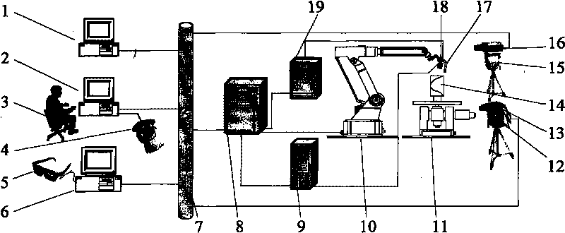
[0016] Specific implementation mode one: combine Figure 1-Figure 3 Describe the present embodiment, the method of the present embodiment is realized by the following steps: Step 1: the macro zoom camera 16 collects two-dimensional video images, and transmits the two-dimensional video images to the macro vision display 1 through the video line, and the operator 3 locally In the central monitoring human-machine interface 2 at the end, the field of view is adjusted through the focus control and the second controllable pan-tilt 15;

[0017] Step 2: The operator 3 operates the space mouse 4 to issue a control command, which is transmitted to the remote robot controller 8 through the industrial Ethernet 7 to control the movement of the remote robot 10, and the robot 10 guides the welding torch 17 to move to 30-40mm above the welding seam At the same time, the robot controller 8 transmits the pose matrix of the welding gun 17 to the central monitoring man-machine interface 2 of the ...

specific Embodiment approach 2

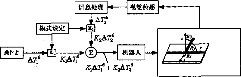
[0025] Specific implementation mode two: combination image 3Describe this embodiment, the degree of freedom weighted fusion algorithm of this embodiment is superimposed by the direct control command of the operator 3 and the visual sensing control command in the robot controller 8 according to the predetermined weight value, and the control commands of the two All degrees of freedom of the robot 10 are affected to jointly change the pose of the welding torch 17, and it is assumed that the driving matrix of the manual control command of the operator 3 is ΔT 1 6 , the weight value is K 1 (01 2 6 , the weight value is K 2 (02 T = K 1 ΔT 1 6 + K 2 ΔT 2 6 ( 0 K 1 1,0 K 2 ...

specific Embodiment approach 3

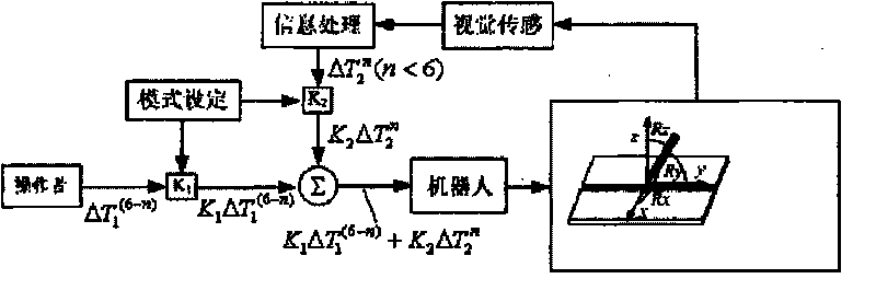
[0026] Specific implementation mode three: combination figure 2 Describe this embodiment, the degree of freedom segmentation algorithm of this embodiment is to divide the six degrees of freedom of the robot, direct control commands and visual sensing control commands respectively control different degrees of freedom, the laser stripes of the laser vision controller 9 hit The surface of the workpiece 14 is reflected on the laser vision sensor working head 18, and the groove information of the weld is extracted through image processing to obtain the position information (X, Y, Z) of the weld feature point, where X is the horizontal direction and Y is the speed , Z is the height, combined with the attitude (Rx, Ry, Rz) of the robot 10 at this time, wherein Rx is the travel angle, Ry is the working angle, and Rz is the spin angle, the drive matrix of the laser vision sensor control command is obtained, set The drive matrix is ​​ΔT 2 n , the weight value is K 2 (02 T...


PUM


Abstract

A man-machine collaboration shared control remote welding method relates to a remote welding method. The invention aims to solve the problems in the prior remote welding that the direct control operation can not be continuously carried out and particularly can not work under the situation of time delay, and an autonomous tracking weld seam can not be welded under the situations of complicated welding environment and irregular groove outline dimension of a weld seam. The remote welding method comprises the following steps: firstly, a macroscopic zooming camera acquires a two-dimensional video image, and the visual field of an operator is adjusted in a central monitoring man-machine interface; secondly, a robot guides a welding gun to reach the upper part of the weld seam; thirdly, the operator tracks the weld seam; fourthly, a workpiece is fixed on a working platform to form the welding environment at the remote end; fifthly, the robot moves towards an initial point of the weld seam; sixthly, the welding gun ensures that arc-length distance parameters of the workpiece are set by the central monitoring man-machine interface; and seventhly, the operator sets a shared control algorithm through the central monitoring man-machine interface.

Description

technical field [0001] The invention relates to a remote welding method. Background technique [0002] Welding applications are indispensable in the maintenance of nuclear power plant equipment, underwater construction of marine engineering, and future space station construction. The limitations of these extreme environments make it difficult for the operator to be present at the scene and directly operate the welding torch or equipment. The traditional welding method cannot be applied, and remote welding must be carried out. Remote welding refers to the remote monitoring and control of welding equipment and welding process by people in a safe environment away from the site according to various sensor information from the site, so as to complete the welding operation. Due to the adaptability of the robot to the environment, it is used as an actuator in research and practical applications. When performing remote welding, the operator usually operates the robot remotely and ...

Claims


Application Information

Patent Timeline
IPC IPC(8): B23K37/00
Inventor 李海超高洪明张广军陈洪堂吴林
Owner HARBIN INST OF TECH
Why Eureka
Try Eureka