Tilting charge and discharge type reducing furnace and reducing method thereof

A technology for charging and discharging materials and reducing furnaces is applied in the field of metal vacuum smelting and reducing furnaces, which can solve problems such as low efficiency and environmental pollution, and achieve the effects of protecting the environment, reducing dust pollution, and reducing labor costs.

Inactive Publication Date: 2010-06-23
青岛荣恒节能设备有限公司
View PDF2 Cites 2 Cited by
  • Summary
  • Abstract
  • Description
  • Claims
  • Application Information

AI Technical Summary

Problems solved by technology

[0009] The purpose of the present invention is to provide a tilting loading and discharging reduction furnace and its reduction method to solve the problems of labor-intensive, environmental pollution and low benefit in the prior art

Method used


Image

  • Tilting charge and discharge type reducing furnace and reducing method thereof
  • Tilting charge and discharge type reducing furnace and reducing method thereof
  • Tilting charge and discharge type reducing furnace and reducing method thereof

Examples


Embodiment Construction

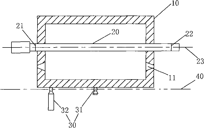
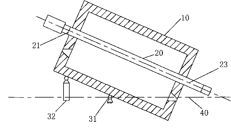
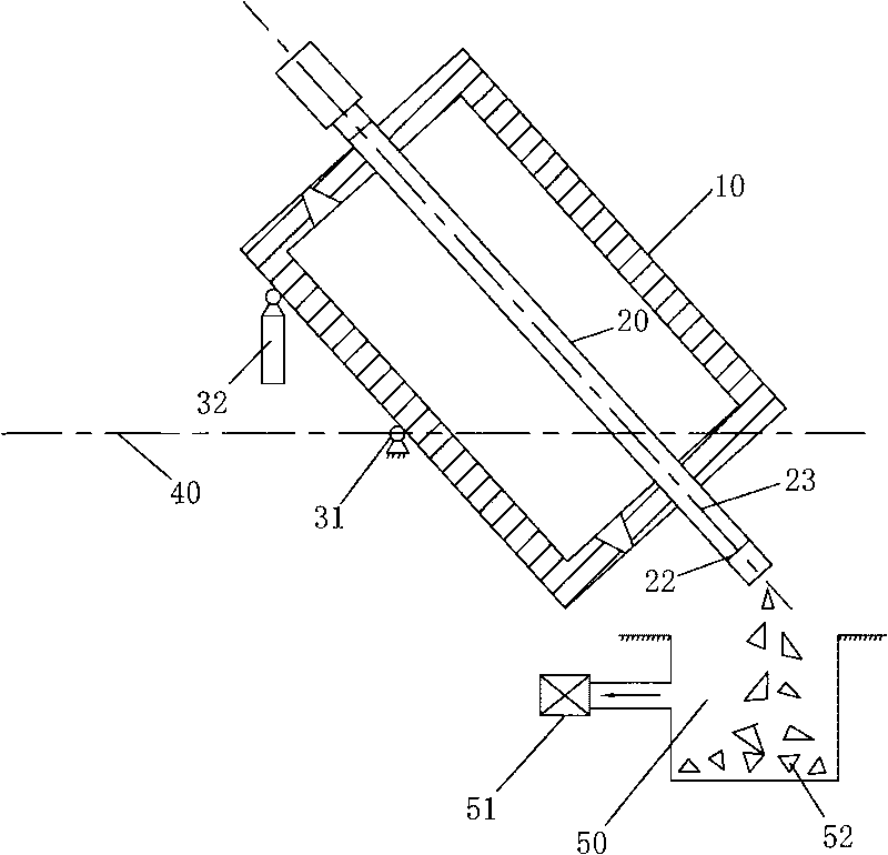
[0043] Such as figure 1 , figure 2 , image 3 As shown, it is a tilting charging and discharging type reduction furnace, which includes a furnace body 10, a reduction tank 20 and a furnace body tilting mechanism 30, wherein:

[0044] The furnace body 10 is provided with a combustion system 11 to provide the high temperature required in the reduction process;

[0045] The reduction tank 20 is installed and fixed in the furnace body 10, both ends of which protrude out of the furnace body 10, one end of the reduction tank 20 is provided with a charging port 21, and the other end is provided with a slag discharge port 22;

[0046] The furnace body tilting mechanism 30 includes: a rotating shaft 31 as a fulcrum of the rotating motion of the furnace body 10 and a lifting mechanism 32 (such as a hydraulic cylinder or an electric screw mandrel) that drives the furnace body 10 to rotate around the rotating shaft 31 . The rotating shaft 31 is arranged horizontally, so that the reduc...


PUM


Abstract

The invention relates to a tilting charge and discharge type reducing furnace and a reducing method thereof. The reducing furnace comprises a furnace body, a furnace tank and a furnace body tilting mechanism, wherein a combustion system is arranged in the furnace body for providing high temperature required for a reducing process; the reducing tank is arranged in the furnace body in a penetrating manner, and two ends thereof extend out of the furnace body, a charging hole is formed at one end of the reducing tank, and a dreg outlet is formed at the other end of the reducing tank; the furnace body tilting mechanism comprises a rotating shaft as a furnace body rotating and moving fulcrum and a lifting mechanism for driving the furnace body to rotate around the rotating shaft; and the rotating shaft is horizontally arranged; and the reducing tank at least can rotate between a horizontal position and an inclined position back and forth. The reducing tank of the tilting charge and discharge type reducing furnace is positioned in the horizontal position during the heating and reducing process and also positioned in the inclined position in a charging and dreg discharging process; and dregs can be automatically discharged by utilizing gravity, so that the production speed is improved, and the labor amount is reduced, thereby facilitating mechanical production.

Description

technical field [0001] The invention relates to a metal vacuum smelting reduction furnace, in particular to a vacuum smelting reduction furnace for smelting metal magnesium or calcium. Background technique [0002] Some alkali metals and alkaline earth metals with high vapor pressure, such as chromium, chromium, magnesium, calcium, etc., can be prepared by metallothermic reduction of silicon, aluminum or their alloys under vacuum conditions. According to the different heating methods, the current silicothermal magnesium smelting can be divided into three types: one is the Pidgeon process (The Pidgeon Process), the other is the French semi-continuous magnesium smelting (The Magnetherm Process), The other is The Bolgano Process in Italy. The former belongs to the external heating silicon thermal magnesium smelting method, while the latter two methods are internal resistance heating silicon thermal magnesium smelting. [0003] Among them, the Pidgeon method is the most widely...

Claims


Application Information

Patent Timeline
Patent Type & Authority Applications(China)
IPC IPC(8): C22B26/20C22B5/16
Inventor 辛卫亚王张福
Owner 青岛荣恒节能设备有限公司
Why Eureka
Try Eureka