
Hyperboloid balance flow gauge

A flowmeter and hyperboloid technology, applied in the field of machinery, can solve the problems of increasing maintenance, changing the cross-sectional area of ​​the pipeline, measuring disorder, etc., to achieve accurate and more effective measurement data, improve measurement accuracy, and reduce momentum loss.

Active Publication Date: 2014-03-05
SHANGHAI KEYONTECHS CO LTD
View PDF3 Cites 0 Cited by
  • Summary
  • Abstract
  • Description
  • Claims
  • Application Information

AI Technical Summary

Problems solved by technology

[0006] 2. The noise of the differential pressure signal is large, resulting in low measurement accuracy and repeatability;
[0007] 3. The throttling of the orifice will make the flow field irregular, requiring a long straight pipe section for rectification;
[0008] 4. When the pipeline is installed horizontally, the impurities at the lower end of the orifice plate cannot flow through, and it is easy to accumulate and change the cross-sectional area of ​​the pipeline, so it is not suitable for measuring dirty, impurity and viscous media;
[0009] 5. The eddy current on the orifice plate and downstream leads to loss of kinetic energy, large permanent pressure loss, and waste of energy;
[0010] 6. The sharp inner edge of the orifice throttle is very thin, which is easy to wear, resulting in measurement errors and shortening the service life;
[0011] 7. The installation site of the project is prone to assembly deviation, wrong direction, and increased maintenance;
[0012] 8. For fluids whose volume is easily affected by temperature and pressure, the sudden shrinkage and throttling of the orifice plate will cause the flow cross-sectional area in the dead zone to be unstable, and cause a large superposition error to the differential pressure signal. For fluids near the critical state, it is very It is easy to cause phase transition and cause measurement disturbance
[0013] There is a kind of cone flowmeter, a throttling circular cone is placed in the center of the fluid pipeline to measure the flow rate, which can also better solve the problem of viscous media and impurity clogging, and has a symmetrical structure, which can reduce the straight pipe section, but the turbulence at the tail of the cone There are many flows, the relative pressure loss is relatively large, and there are structural safety hazards

Method used


Image

  • Hyperboloid balance flow gauge
  • Hyperboloid balance flow gauge
  • Hyperboloid balance flow gauge

Examples


Embodiment Construction

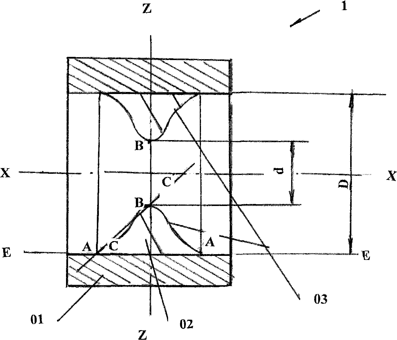
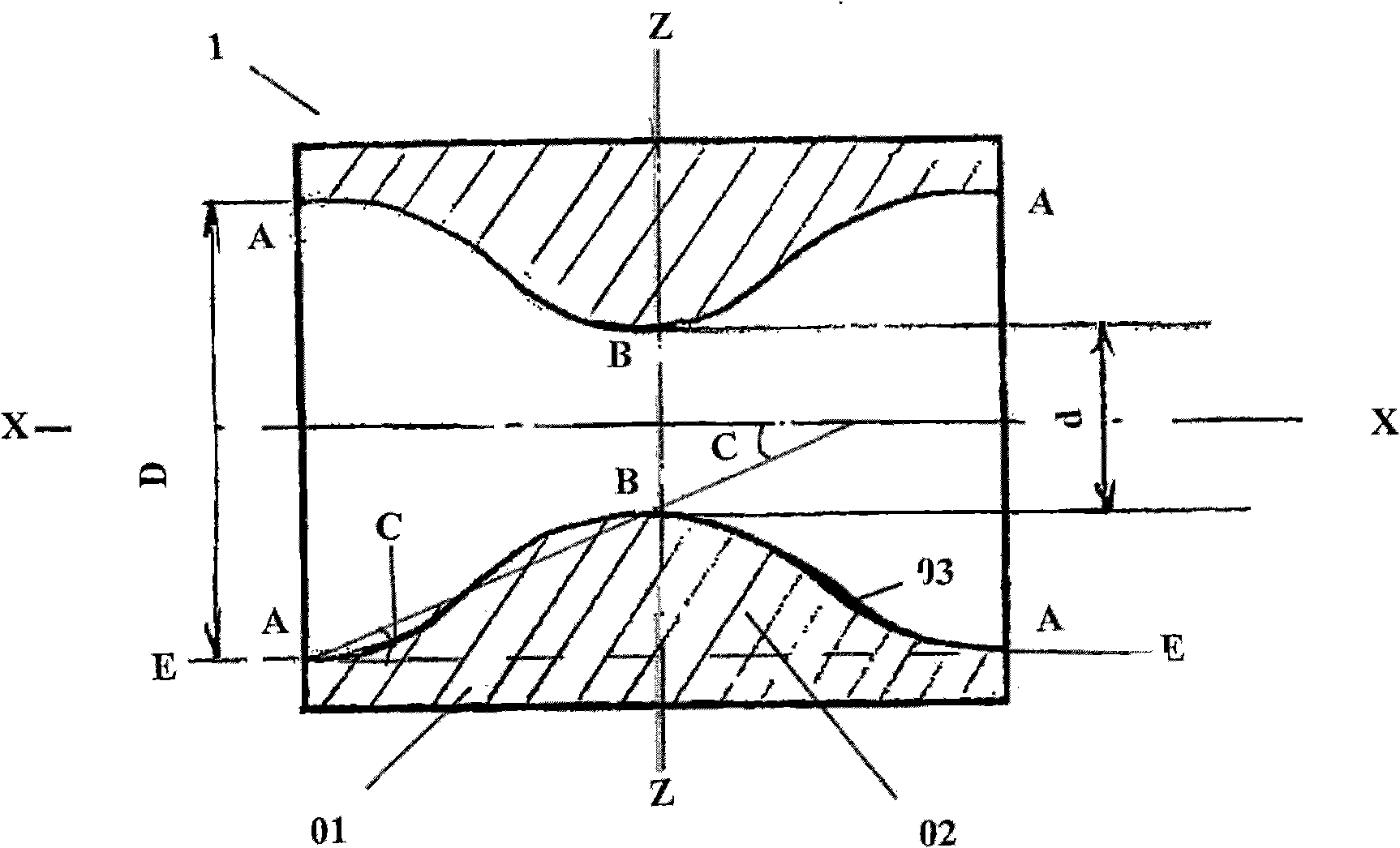
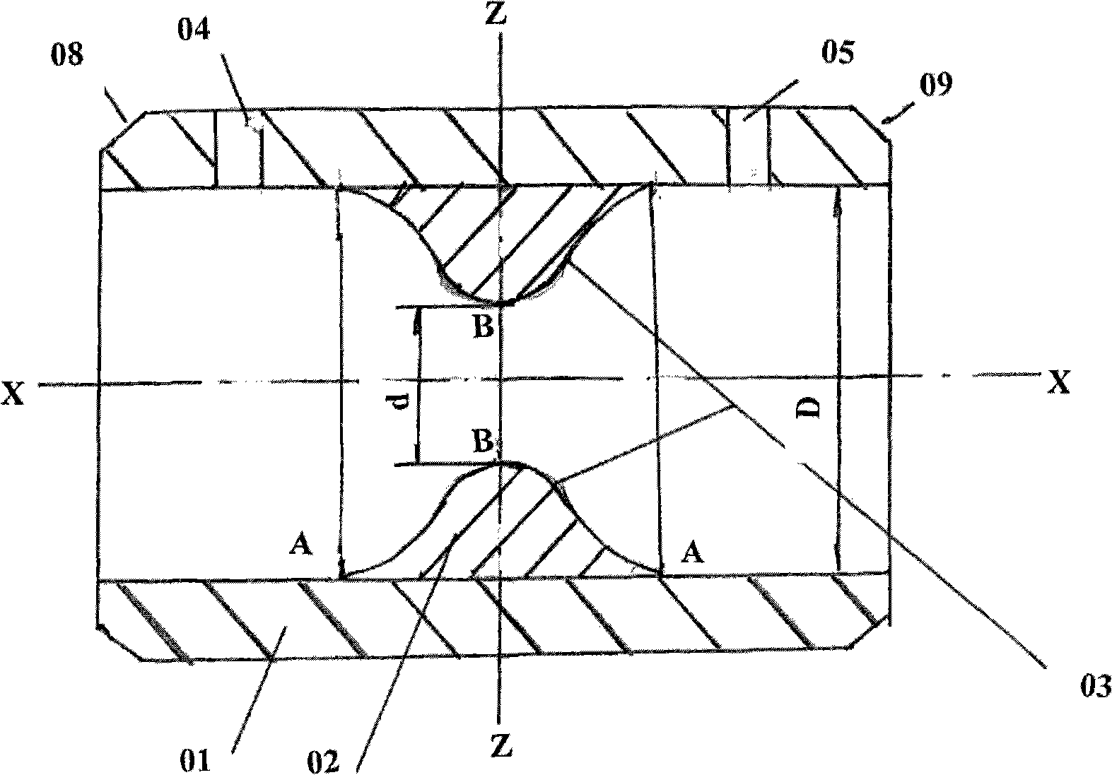
[0024] The flowmeter of the present invention can be called a hyperboloid balanced flowmeter according to the structure, and the flowmeter is installed in the channel through which the fluid passes so as to cross the pipeline, or installed in two flanges connecting two adjacent pipelines , communicate with the pipeline through the hole in the flange.

[0025] The structural features of the flowmeter of the present invention will be described in further detail below in conjunction with the accompanying drawings.

[0026] The structure of the flowmeter of the present invention belongs to the differential pressure orifice flowmeter, and the structure of the differential pressure orifice flowmeter is well known to those skilled in the art. Therefore, only the structure of the flowmeter of the present invention-a longitudinal sectional view is provided here , to be explained.

[0027] refer to figure 1 , figure 1 It is an explanatory view of the structure of the flowmeter of the...


PUM


Abstract

A hyperboloid balance flowmeter comprises a pipeline piece (01) and an internal throttling piece (02) mounted on the internal wall of the pipeline piece (01). The guide flow surface (03) of the internal throttling piece (02) is a cambered surface. The resistance of the flowmeter to fluid is reduced and the measuring precision is improved.

Description

technical field [0001] The invention belongs to the field of machinery, in particular to a device for measuring fluid flow in pipelines. Background technique [0002] The existing standard orifice flowmeter is a throttling differential pressure flow measuring device composed of a standard orifice plate and a differential pressure transmitter. It can measure the flow of gas, steam, liquid and natural gas. It is widely used in petroleum, chemical, Process control and flow measurement in the fields of metallurgy, electric power, heat supply, water supply, steam supply, etc., are used in the largest number. [0003] The working principle of the orifice plate flowmeter is to add an orifice plate throttling device in the pipe filled with fluid flowing through the pipe, causing the edge to shrink near the orifice plate throttling element, increasing the flow rate, and generating a static pressure difference between its upstream and downstream sides. Under the condition of known wo...

Claims


Application Information

Patent Timeline
Patent Type & Authority Patents(China)
IPC IPC(8): G01F1/40
CPCG01F1/42G01F1/44G01F1/40
Inventor 周人
Owner SHANGHAI KEYONTECHS CO LTD
Learn More