
Liquid filling device with adjustable fill quantity

A filling device and adjustable technology, applied in liquid bottling, liquid treatment, packaging, etc., can solve problems such as easy to get dirty, inconvenient cleaning of the filter screen, and many wearing parts, and achieve fast filling speed and reduce The hidden danger of product pollution and the effect of high filling accuracy

Inactive Publication Date: 2010-06-30
GUANGZHOU TECH LONG PACKAGING MACHINERY CO LTD
View PDF1 Cites 7 Cited by
  • Summary
  • Abstract
  • Description
  • Claims
  • Application Information

AI Technical Summary

Problems solved by technology

The filling machine has the following defects: (1) The mechanical structure is complex, there are many sanitary dead ends, and there are many wearing parts, which cannot meet the sanitary requirements; (2) It is inconvenient to change the filling capacity, and the capacity change has limitations; (3) The filling accuracy is not high and it is difficult to adjust
However, the filling device has the following problems: (1) The cylinder driving device is directly connected to the blocking rod, which easily causes product contamination; (2) In order to avoid turbulent flow of the outflowing liquid, a filter assembly is installed at the lower end of the discharge nozzle, Because the filter screen assembly is easy to retain liquid and is exposed to the air, it is easy to get dirty, resulting in product contamination, and the filter screen is not easy to clean; (3) There is a long gap between the connecting sleeve and the outlet of the discharge nozzle. The distance will not only cause control lag and inaccurate filling, but also, when the valve is closed, it is easy to have residual liquid in this section. It is unhygienic when it enters the product; (4) Immediate nitrogen filling protection cannot be realized after filling, and it cannot meet the quality assurance requirements of high-end products

Method used


Image

  • Liquid filling device with adjustable fill quantity
  • Liquid filling device with adjustable fill quantity
  • Liquid filling device with adjustable fill quantity

Examples


Embodiment Construction

[0020] The embodiments of the present invention will be described in detail below in conjunction with the drawings:

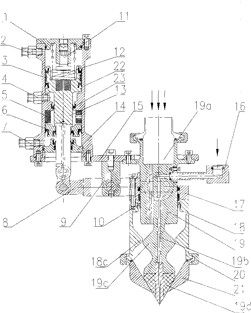
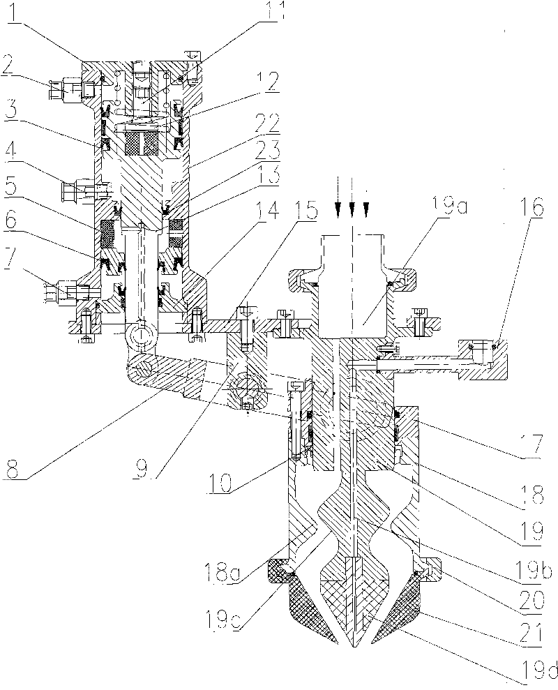
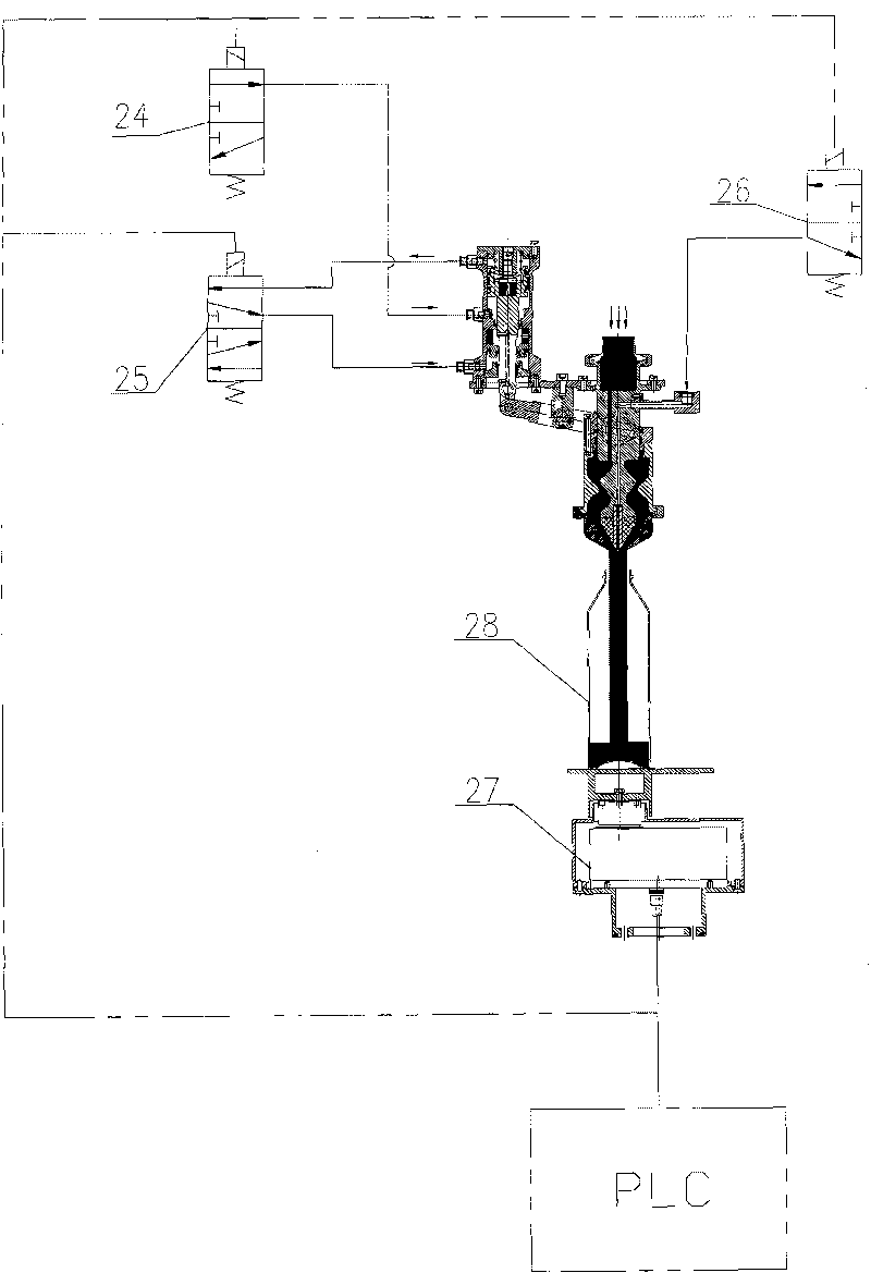
[0021] see figure 1 , figure 2 , The liquid filling device with adjustable filling volume of the present invention is mainly composed of a mounting seat 15 and a cone filling valve installed on the mounting seat 15, a cylinder driving device and a lever transmission device. Among them, the conical filling valve is fixed under the mounting seat 15, and is composed of a valve housing and a valve core 19 installed in the valve housing. The valve housing is composed of an upper sleeve 18 and a lower filling nozzle 21 connected by a connecting piece 20. A first convex ring 18a is provided on the inner wall of the middle of the sleeve 18, and the axial section of the first convex ring 18a is tapered. A tapered discharge port is provided in the center of the filling nozzle 21. The lower end of the valve core 19 is provided with a tapered valve head 19d, which is in a l...


PUM


Abstract

The invention discloses a liquid filling device with adjustable fill quantity, comprising a tapered filling valve fixed on a mounting seat and a driving device, wherein the tapered filling valve comprises a valve casing and a valve core capable of moving in the valve casing relatively to the valve casing, the lower end of the valve core is provided with a tapered valve head, the valve casing is provided with a tapered discharge hole, and the discharge hole is matched with the valve head; the liquid filling device is characterized in that the valve casing or the valve core is connected with the driving device through a lever transmission device. In the invention, a driving cylinder is completely separated with the filling valve, thereby reducing hidden trouble of product pollution; the unique valve-core structure can ensure that the filling products are bunched turbulently under the condition of without a filter screen member, thus being more in accordance with sanitary requirement; in addition, the device has the function of charging nitrogen and can meet the requirement of filling high-grade oils.

Description

Technical field [0001] The invention relates to a liquid filling device, in particular to a liquid filling device with an adjustable filling volume. Background technique [0002] At present, most of the volumetric (piston) filling machines are used to fill edible oil. The working principle of volumetric (piston) filling machines is: a piston is driven by a cylinder to extract and eject liquid materials, and the cylinder is controlled. The filling volume can be adjusted by the stroke of The filling machine has the following shortcomings: (1) The mechanical structure is complex, there are many sanitary blind spots, and there are many vulnerable parts, which cannot meet the sanitary requirements; (2) It is inconvenient to change the filling capacity, and the capacity change has limitations; (3) The filling accuracy is not high and it is difficult to adjust. In order to solve the above problems, Chinese patent CN2740587 discloses a weighing and filling device, which includes a conn...

Claims


Application Information

Patent Timeline
Patent Type & Authority Applications(China)
IPC IPC(8): B67C3/28
Inventor 樊缔潘海丰李正良
Owner GUANGZHOU TECH LONG PACKAGING MACHINERY CO LTD
Learn More