
Excitation type high energy power supply apparatus

A power supply device and high-energy technology, applied in circuits, electrical components, lead-acid batteries, etc., can solve the problems of lead-acid battery increase in heat energy, waste of resources, waste of electric energy, etc., achieve uniform distribution of current density, save charging costs, The effect of reducing production costs

Inactive Publication Date: 2013-03-20
KUSN JINDING NEW ENERGY TECH
View PDF0 Cites 0 Cited by
  • Summary
  • Abstract
  • Description
  • Claims
  • Application Information

AI Technical Summary

Problems solved by technology

[0005] It is precisely because of the difference between the positive plate and the negative plate in the lead-acid battery that the positive current and the negative current must be collected and conducted separately, so it is necessary to use a metal grid or a metal bone grid to collect charges on the positive plate and the negative plate respectively. , and then conduct them through their respective tabs, and finally conduct the positive current and the negative current separately through the bus bar. It can be seen that the internal structure of the traditional lead-acid battery is not only complicated but also uses a large amount of metal (metal grid , metal bone grid, tabs and busbars, etc.) conduction means, which increases the internal resistance of the lead-acid battery, which further leads to an increase in the internal friction of the lead-acid battery and increases the heat generated by the lead-acid battery
When the lead-acid battery is discharged with a large current, the internal resistance increases sharply, and the voltage and current drop rapidly, so that the battery cannot fully discharge electric energy instantly, and due to the increase in internal resistance, the battery converts part of the electric energy into heat energy, resulting in The waste of electric energy and the heat generated at the same time can easily damage the battery
Furthermore, due to the increase of the internal resistance of the battery, the battery cannot be charged with a large current, and it needs a long time of slow charging, which is inconvenient for users to use. After the lead-acid battery is discharged, a large amount of lead sulfate is produced, and the lead sulfate forms resistance, which further increases The internal resistance of the battery makes it difficult to charge and discharge the battery, so the service life of the existing battery is very short
[0006] Under normal circumstances, the capacity of lead-acid batteries is generally designed according to the amount of active material (lead paste), and the negative electrode is designed to match the positive electrode, that is, it is designed to assist the positive electrode, because the negative electrode has no capacity, only the positive electrode releases Therefore, the capacity of the storage battery is limited by the capacity of the positive electrode and can only produce a localized capacity. The utilization rate of the active matter of the existing storage battery does not exceed 35%, which greatly wastes resources
[0007] In addition, in the production of existing lead-acid batteries, it is necessary to use chemical formation technology to make plates, and further operations such as welding the tabs and busbars of each plate are required. During the above operations, lead smoke and lead dust are formed , acid sewage and acid mist and other toxic and harmful substances affect human health and pollute the ecological environment

Method used


Image

  • Excitation type high energy power supply apparatus
  • Excitation type high energy power supply apparatus
  • Excitation type high energy power supply apparatus

Examples


Embodiment Construction

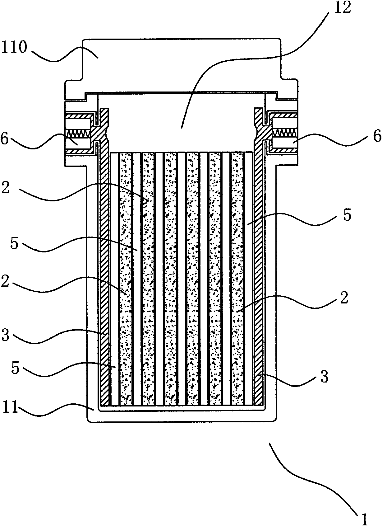
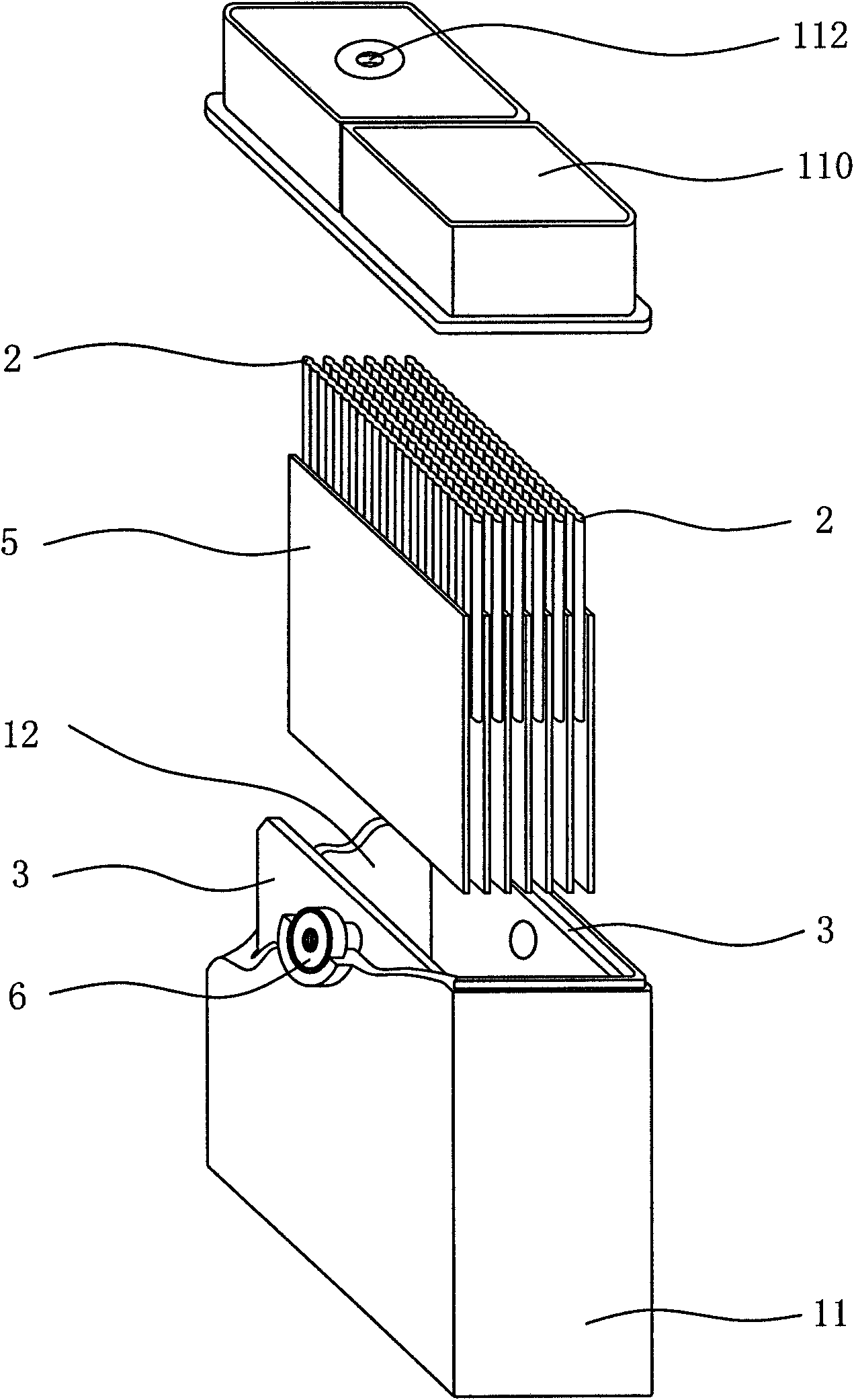
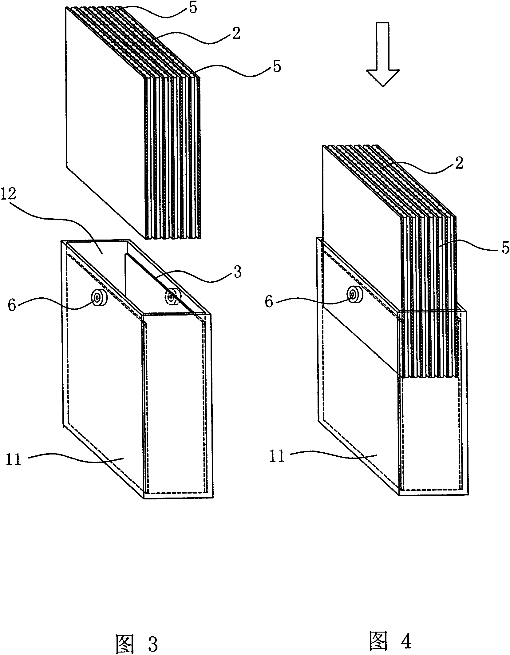
[0117] Referring to all the accompanying drawings, there is an exciting high-energy power supply device, including a storage battery with output negative voltage or positive voltage, and the storage battery with output negative voltage or positive voltage includes a casing, a cover located above the casing, and a At least one battery cell tank, at least two electrical energy bodies, at least one separator, at least two collectors and at least two external terminals filled with electrolyte in the housing, the electrical energy body, separator and collector Located in the cell of the battery cell, the electric energy body is isolated from the electric energy body by the spacer, the current collectors are respectively connected to the external terminals, and the electric energy body is first placed in the formation tank Charging, or charging after the battery is assembled, is usually called formation. The battery in the present invention is discharged directly without internal for...


PUM


Abstract

The invention relates to an excitation type high energy power supply apparatus, which is characterized in that a storage battery having an output negative voltage or an output positive voltage comprises a housing, a cover positioned above the housing, at least a storage battery monomer groove arranged inside the housing and filled with an electrolyte, at least two electric energy bodies, at least a separator, at least two current collectors and at least two external connection terminals, wherein the electric energy bodies, the separator and the current collectors are positioned inside the storage battery monomer groove, the electric energy bodies are separated through the separator, and the current collectors are respectively connected with the external connection terminals, such that external leakage of lead dust, lead smoke, acid waste water and acid mist during production can be effectively avoided, pollution hidden danger is effectively eliminated, pollution treatment equipment installation is effectively reduced, production investment is substantially saved, environment is protected, pollution is eliminated, charging cost is saved, a structure is simple, standards of workpieces for forming parts are single, assembly line production is achieved, labor is saved, production cost is reduced, and the apparatus is applicable for large mass production.

Description

technical field [0001] The invention relates to the field of power supply and can be used in wind energy, solar energy, communication, transmission and transformation systems, power plants, automobiles, pure electric vehicles, motorcycles, mopeds, mines, household appliances, lighting and the like. Background technique [0002] With the increasing scarcity of fossil energy, fossil energy has become an extreme problem faced by the world. In order to save energy, in 1859 the Frenchman Plant invented a kind of storage battery. The skin, separated by a rubber strip in the middle, is soaked in 10% sparse acid, and undergoes forward charging, stop, and reverse charging, and so on. The Englishman Sellon (Sellon) invented the lead-antimony alloy grid. This grid is combined with the Fur powder coating method to produce the so-called paste-coated plate. [0003] Since the 10s of the 20th century, the development of the automobile industry and the telephone industry has greatly promot...

Claims


Application Information

Patent Timeline
IPC IPC(8): H01M10/12H01M2/20H01M2/24H01M50/529
CPCY02E60/126Y02E60/10Y02P70/50
Inventor 于文学
Owner KUSN JINDING NEW ENERGY TECH
Learn More