Single spiral air-duct-type biomass boiler

A technology of spiral wind and biomass, which is applied in the direction of combustion method, block/powder supply/distribution, solid fuel combustion, etc., can solve the problem of increasing the process links of biomass crushing-mixing-forming-drying and unfavorable promotion Application, high boiler manufacturing costs and other issues, to achieve the effect of solving energy shortage and environmental pollution, great potential for popularization and application, and reasonable structural design

Inactive Publication Date: 2010-06-30
宋传太
View PDF0 Cites 1 Cited by
  • Summary
  • Abstract
  • Description
  • Claims
  • Application Information

AI Technical Summary

Problems solved by technology

[0002] When traditional boilers use biomass as fuel, the biomass is pulverized and then mixed-molded-dried. The problem in the use of this shaped fuel is: it increases the biomass in crushing-mixing-molding-drying process. In addition, the unit price of this formed biomass fuel is equivalent to the price of coal with the same calorific value, and it is even higher than the coal price in coal-producing areas
Therefore, the original biomass particle molding process has high production costs, which is difficult for users to accept from an economic point of view, which is not conducive to popularization and application.
In addition, traditional biomass boilers need to be equipped with grate bars, grate and grate transmission mechanisms, etc. Due to the limitation of this structure, the manufacturing cost of the boiler is relatively high

Method used


Image

  • Single spiral air-duct-type biomass boiler
  • Single spiral air-duct-type biomass boiler

Examples


Embodiment 1

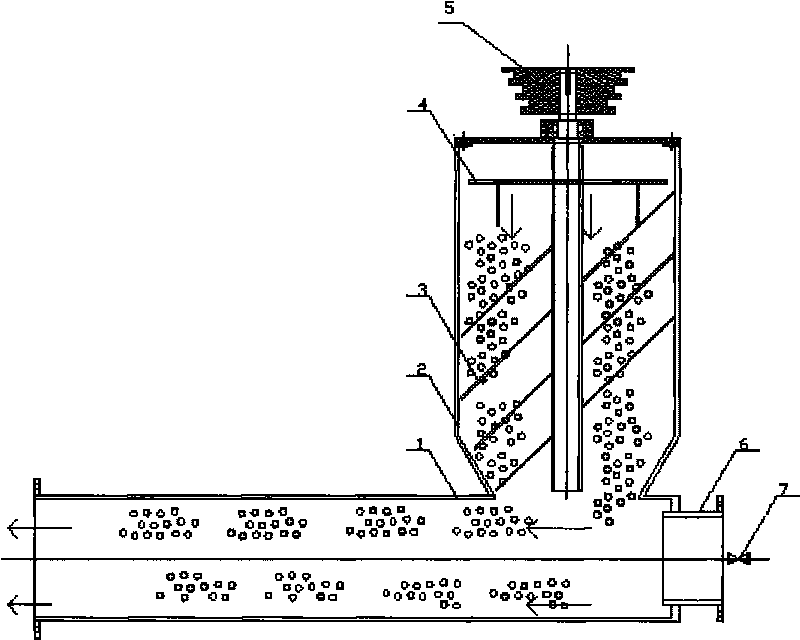
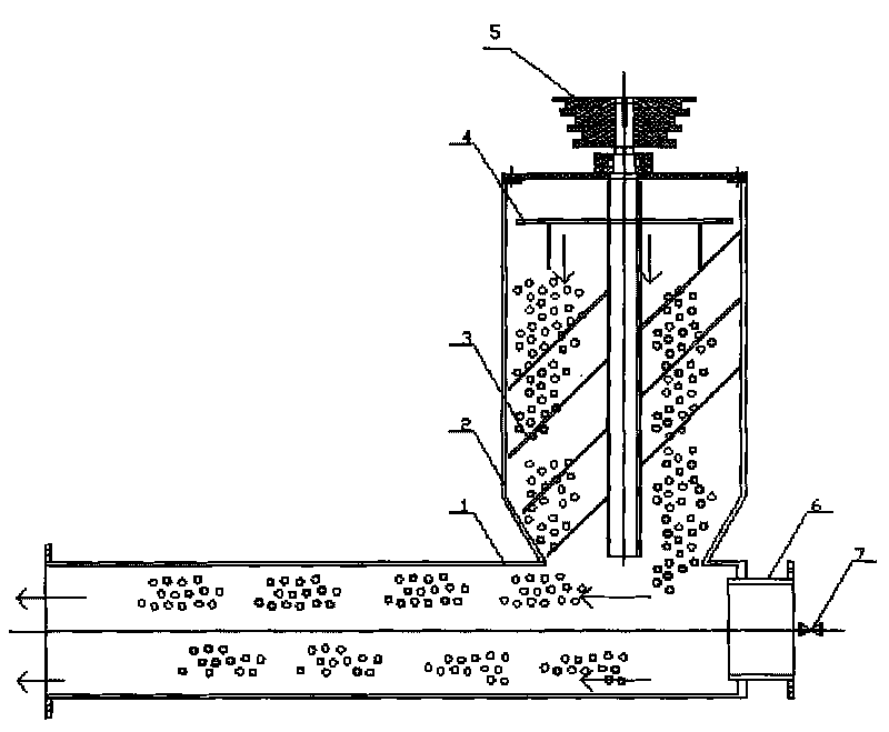
[0017] Such as figure 1 As shown, the biomass single-spiral air cylinder boiler includes a furnace body, a combustion chamber, and a fuel conveyor. The front end of the fuel cylinder 1 is connected to the boiler combustion chamber, and the end of the fuel cylinder 1 is connected to the fan through the fan interface 6. 7 is located at the fan interface 6, and the fuel bucket 2 is provided with a screw propulsion device. The screw propulsion device 3 is composed of a screw rod and blades installed on it. The upper end of the screw rod is connected with the belt pulley 5 of the speed regulating motor. The motor is adjusted to drive and adjust the rotation of the screw pushing device 3, and the upper part of the fuel hopper 2 is provided with a distributor 4, and the fuel hopper 2 is also provided with a cover plate. figure 1 The particles in the middle fuel cylinder and the fuel hopper represent biomass fuel, and the arrows represent the feeding direction.

[0018] According to ...


PUM


Abstract

The invention relates to a single spiral air-duct-type biomass boiler, which comprises a furnace body, a burner and a fuel conveyor; the single spiral air-duct-type biomass boiler is characterized in that: the front end of a fuel tube is connected to a boiler combustion chamber, the terminal end of the fuel tube is connected to an air blower through an air blower connector, an air volume control valve is arranged at the position of the air blower connector, a fuel hopper is provided with a spiral propeller inside, a screw rod is connected to a speed adjusting motor through a belt pulley arranged on the top of the screw rod, a distributor is arranged on the inner upper part of the fuel hopper. The invention transfers biomass fuel which is processed into bar shape or coarse powder shape into the fuel hopper, transfers the biomass fuel into the fuel tube through the spiral propeller, the volume and speed of the fuel transferred into the combustion chamber are respectively controlled by the speed adjusting motor and the air blower, and the fuel is blown into the boiler combustion chamber by wind force, so as to form suspension burning. The single spiral air-duct-type biomass boiler has the advantages that grate bars, furnace grates or transmission mechanism for the furnace grate does not need to be designed, thus reducing manufacturing cost of the boiler; waste straws are adopted as reusable energy for fully utilization, thereby solving the current energy shortage, and environmental pollution problems.

Description

technical field [0001] The invention relates to a biomass single-spiral air drum boiler, which belongs to the technical field of biomass boiler burners and conveying devices. Background technique [0002] When traditional boilers use biomass as fuel, the biomass is pulverized and then mixed-molded-dried. The problem in the use of this shaped fuel is: it increases the biomass in crushing-mixing-molding-drying process. Moreover, the unit price of this formed biomass fuel is equivalent to the price of coal with the same calorific value, and it is even higher than the coal price in coal-producing areas. Therefore, the original biomass particle molding process has high production costs, which is difficult for users to accept from an economic point of view, and is not conducive to popularization and application. In addition, traditional biomass boilers need to be equipped with grates, grates, and transmission mechanisms for the grates. Due to the limitation of this structure, the...

Claims


Application Information

Patent Timeline
IPC IPC(8): F23B40/00F23K3/00
Inventor 宋传太
Owner 宋传太
Why Eureka
Try Eureka