
A method for reducing the dose penumbra of the trailing edge of the broadened Bragg peak of the ion beam when irradiated with high-energy ion beams

An ion beam and high-energy technology, which is applied in the field of high-energy ion beam irradiation, can solve the problems of increasing the number of times of ion beam energy and increasing the irradiation time

Active Publication Date: 2011-12-28
INST OF MODERN PHYSICS CHINESE ACADEMY OF SCI
View PDF0 Cites 0 Cited by
  • Summary
  • Abstract
  • Description
  • Claims
  • Application Information

AI Technical Summary

Problems solved by technology

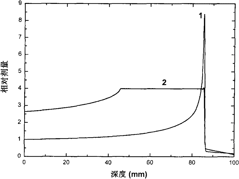
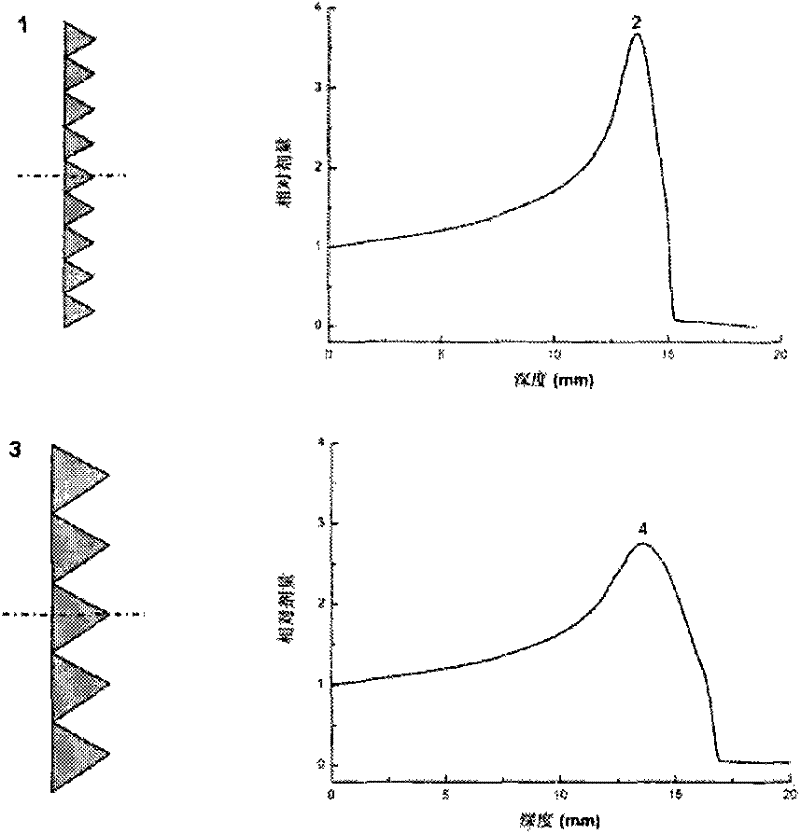
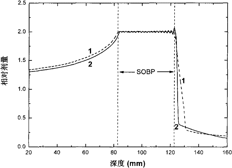
In this way, the ion beam Bragg peak is broadened. If the micro-ridge filter slightly broadens the ion beam Bragg peak into a Gaussian distribution with a larger half-maximum width (FWHM), then these micro-broadened peaks are superimposed to form the final required width SOBP The trailing edge dose penumbra is also larger; if the micro-ridge filter slightly broadens the Bragg peak of the ion beam into a Gaussian distribution, the FWHM is smaller, although the trailing edge dose half of the final required width SOBP is formed by the superposition of these small broadened peaks. The shadow is also small, but since more micro-broadened peaks are superimposed to form the SOBP with the required width, the times of changing the ion beam energy are correspondingly increased, so the irradiation time will be significantly increased, especially when the synchrotron is used. The increase in irradiation time is especially noticeable when time-structured pulsed ion beam irradiation

Method used


Image

  • A method for reducing the dose penumbra of the trailing edge of the broadened Bragg peak of the ion beam when irradiated with high-energy ion beams
  • A method for reducing the dose penumbra of the trailing edge of the broadened Bragg peak of the ion beam when irradiated with high-energy ion beams
  • A method for reducing the dose penumbra of the trailing edge of the broadened Bragg peak of the ion beam when irradiated with high-energy ion beams

Examples


Embodiment Construction

[0037] Using the 235MeV / u carbon ion beam provided by the Lanzhou Heavy Ion Research Facility (HIRFL-CSR) of the Institute of Modern Physics, Chinese Academy of Sciences, we tested the method of the present invention at the HIRFL-CSR deep tumor heavy ion therapy terminal. The irradiation device used in the test is as follows Figure 4 As shown, the miniature ridge filter is placed vertically on the beam scanning secondary magnet (1), ion detector (2) (NE102, Hamamatsu, Japan), and range shifter (5) (RS05, AEC, Japan) In the center of the beam axis, and placed in front of the range shifter (5), a water tank (MP3-P, PTW Company of Germany) and an ionization chamber (Markus-23343, PTW Company of Germany) were set at the isocenter of the irradiation device ) to measure the depth dose distribution.

[0038] In this test, two micro-ridge filters of 4mmFWHM and 10mmFWHM were used for the micro-ridge filter respectively. First, the 4mmFWHM micro-ridge filter was used to perform two i...


PUM


Abstract

The invention relates to a method for reducing the dose penumbra of the trailing edge of the Bragg peak broadened by the ion beam by using high-energy ion beam irradiation. The ridge filter is placed vertically in the beam axis between the beam scanning secondary magnet, the ion detector, and the range shifter, and is placed between the ion detector and the range shifter, and the beam scans the secondary magnet The ion beam forming a uniform irradiation field is irradiated through the micro-ridge filter by first using the micro-ridge filter FWHM1 to irradiate the depth of the desired SOBP, and then replacing the micro-ridge filter with the micro-ridge filter FWHM2 The other part of SOBP is irradiated by FWHM1. The present invention can give full play to the advantages of energy deposition locality during ion beam irradiation, and can reduce the dose penumbra of the trailing edge of the Bragg peak of the ion beam when implementing three-dimensional conformal irradiation, and at the same time reduce the irradiation time. It has a wide range of application values ​​in beam irradiation material modification, irradiation breeding and radiotherapy plasma beam irradiation technology.

Description

technical field [0001] High-energy ion beams (protons and heavy ions) have been widely used in material modification, mutation breeding, and radiation therapy, resulting in various ion beam irradiation techniques. The invention relates to a high-energy ion beam irradiation technology, in particular to a method for reducing the dose penumbra of the trailing edge of the broadened Bragg peak of the ion beam during irradiation with the high-energy ion beam. Applying this method can minimize the dose penumbra of the ion beam broadening the trailing edge of the Bragg peak, that is, increase the dose descending gradient of broadening the trailing edge of the Bragg peak. Background technique [0002] In the application of high-energy ion beam (proton and heavy ion) irradiation, it is often necessary to broaden the sharp Bragg peak of the monoenergetic ion beam to form a high-dose area with a certain width and uniformity, that is, the broadened Bragg peak (spread-out Bragg peak, SOB...

Claims


Application Information

Patent Timeline
Patent Type & Authority Patents(China)
IPC IPC(8): G21K5/04
Inventor 李强刘新国戴中颖金晓东吴庆丰李萍叶飞徐瑚珊肖国青
Owner INST OF MODERN PHYSICS CHINESE ACADEMY OF SCI
Learn More