MGDM multimode optical fiber communication system and method based on ICA signal separation algorithm
An optical fiber communication system and multi-mode optical fiber technology, applied in the field of communication, can solve the problems of bandwidth occupation, difficult hardware implementation, and large amount of calculation
- Summary
- Abstract
- Description
- Claims
- Application Information
AI Technical Summary
Problems solved by technology
Method used
Image

Examples
Embodiment 1
[0049] Embodiment 1, digital video and digital signal transmission simultaneously
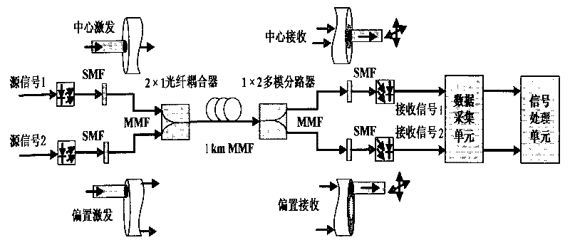
[0050] MGDM is a relatively new technology, and there is no corresponding commercial dedicated device. The present invention has set up the actual system that is easy to realize, sets up the (IM-DD) MGDM experiment system of a 2 * 2 intensity modulation-direct detection, as figure 2 shown.
[0051] The manufacturing method of the mode multiplexer is as follows: the central excitation connector is made by fusion splicing the single-mode fiber (SMF) and the gradient multimode fiber (GI-MMF) to the center (or the eccentricity is 0 μm) to achieve low The excitation of the first-order mode group; the bias excitation connector is made by welding SMF and GI-MMF with an eccentricity of about 26 μm, which is used to realize the excitation of the higher-order mode group. Use a 2×1 fused tapered multimode fiber coupler with a splitting ratio of 50 / 50 to couple the separately excited low-order mode grou...
Embodiment 2、70
[0053] Embodiment 2, CMI codes of 70Mb / s and 140Mb / s are simultaneously transmitted and demultiplexed
[0054] (1) Separation of mixed signals using symmetric orthogonalization FstICA algorithm based on negative entropy
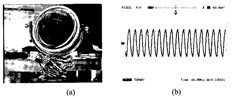
[0055] The 70Mb / s and 140Mb / s CMI code digital signals are simultaneously transmitted using the above-mentioned MGDM test device. These two digital signals are generated by the PTA5102-002 signal source and the random code generator of HP 37717A respectively, and are processed by the signal processing module at the receiving end. Figure 5 is the original digital signal image before transmission. Figure 6 (a) is the received signal image after transmission by the system (the eccentricity of the offset detection connector is 26 μm), the upper part of the figure is the received 70Mb / s signal, and the lower part is the 140Mb / s signal. As a comparison, in order to observe the transmission effect when the receiving end chooses to change the detection position, ...
PUM
 Abstract
Description
Claims
Application Information
 - R&D
- Intellectual Property
- Life Sciences
- Materials
- Tech Scout
- Unparalleled Data Quality
- Higher Quality Content
- 60% Fewer Hallucinations
Browse by: Latest US Patents, China's latest patents, Technical Efficacy Thesaurus, Application Domain, Technology Topic, Popular Technical Reports.
© 2025 PatSnap. All rights reserved.Legal|Privacy policy|Modern Slavery Act Transparency Statement|Sitemap|About US| Contact US: help@patsnap.com