Combined drum-type exposure control method and image sensor used by same

An image sensor and exposure control technology, which is applied in image communication, TV, color TV components, etc., can solve the problems of long cycle and slow system response, and achieve the effect of short response time, full utilization rate and high system efficiency.

Active Publication Date: 2010-06-30
BRIGATES MICROELECTRONICS KUNSHAN
View PDF1 Cites 21 Cited by
  • Summary
  • Abstract
  • Description
  • Claims
  • Application Information

AI Technical Summary

Problems solved by technology

[0011] The technical problem solved by the present invention lies in the fact that in the existing CMOS image sensor multi-exposure control method, when performing multiple exposure imaging, the cycle is too long and the system response is too slow

Method used


Image

  • Combined drum-type exposure control method and image sensor used by same
  • Combined drum-type exposure control method and image sensor used by same
  • Combined drum-type exposure control method and image sensor used by same

Examples


Embodiment Construction

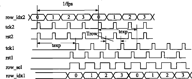
[0028] In the prior art, when multiple imaging is required, after the progressive exposure of each frame of a single image is completed, the exposure time texp needs to be adjusted and changed before the next imaging is performed. If the imaging rate needs to be accelerated, the working rate of the image sensor needs to be increased, but the efficiency of compressing the shortest row processing time only by increasing the operating frequency of the image sensor is not high. This is because the exposure time texp of the target image is set according to its scene conditions, and imaging can be realized as long as it is within the working range of the image sensor. However, the performance of the circuit system of the image sensor only determines the shortest row processing time. In general, the row processing of the image sensor is always carried out row by row. When performing a row of exposure and reading, the pixel units corresponding to other rows are in an idle state. There...


PUM


Abstract

The invention discloses a combined drum-type exposure control method and an image sensor used by the same. The combined drum-type exposure control method comprises the following steps of: alternately carrying out multiple drum-type exposure; outputting a plurality of images by the image sensor in single frame period through different exposure parameters; and integrating a frame of image with a large dynamic range. The invention can effectively shorten the time interval of adjacent times of imaging, fully utilizes idle circuit resources of the image sensor during exposure reading, and has the advantages of high system efficiency, full utilization rate and short reaction time of an output image.

Description

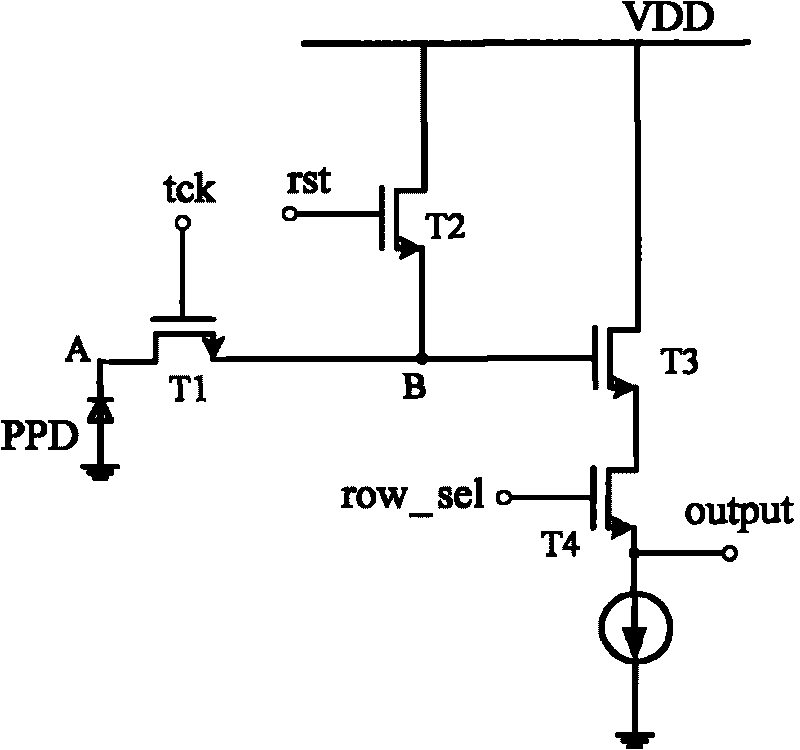
technical field [0001] The present application relates to the field of CMOS (Complementary Metal Oxide Semiconductor) image sensors, in particular to a combined drum exposure control method and an image sensor. Background technique [0002] A CMOS image sensor (CIS), which is a semiconductor device that converts an optical image from an optical signal to an electrical signal, employs a switching mode to sequentially detect pixel outputs by providing a predetermined number of MOS transistors to each pixel. [0003] The Chinese patent with the publication number CN101212580A discloses a typical CMOS image sensor with four-tube structure, and the pixel unit circuit diagram of the sensor is as follows: figure 1 shown. It mainly includes a photodetector PDD, a transmission tube T1, a reset tube T2, a source follower T3, and a selection tube T4. The photodetector PDD includes a photodiode that generates charge from light energy and integrates the charge at point A. The transfer ...

Claims


Application Information

Patent Timeline
Patent Type & Authority Applications(China)
IPC IPC(8): H04N5/335
Inventor 黄碧珍郑炜曹庆红
Owner BRIGATES MICROELECTRONICS KUNSHAN
Why Eureka
Try Eureka