Variable valve timing-phase controller

A phase controller and valve timing technology, applied in the direction of machine/engine, engine components, mechanical equipment, etc., can solve the problems of phase locking, the rotor cannot be rotated, the locking pin is stuck in the locking hole and cannot come out, etc. Achieve high thermal efficiency and improve accuracy

Inactive Publication Date: 2010-07-07
SHANGHAI JIAO TONG UNIV
View PDF1 Cites 27 Cited by
  • Summary
  • Abstract
  • Description
  • Claims
  • Application Information

AI Technical Summary

Problems solved by technology

But there is a risk: when the pressure oil pressure flowing into the oil chamber is large enough to push the vane (camshaft) to rotate but has not fully pushed the locking pin out of the locking position, the rotation tendency of the rotor will press the locking pin on the One side of the locking hole, the locking pin will be stuck in the locking hole and cannot come out, so the rotor cannot rotate
[0004] To sum up, there is an urgent need for a technology at this stage that can solve the problems of phase lock and inability to unlock when starting

Method used


Image

  • Variable valve timing-phase controller
  • Variable valve timing-phase controller
  • Variable valve timing-phase controller

Examples


Embodiment Construction

[0015] The embodiments of the present invention are described in detail below. This embodiment is implemented on the premise of the technical solution of the present invention, and detailed implementation methods and specific operating procedures are provided, but the protection scope of the present invention is not limited to the following implementation example.

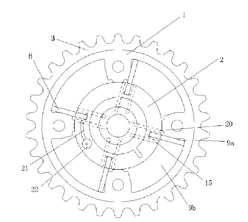
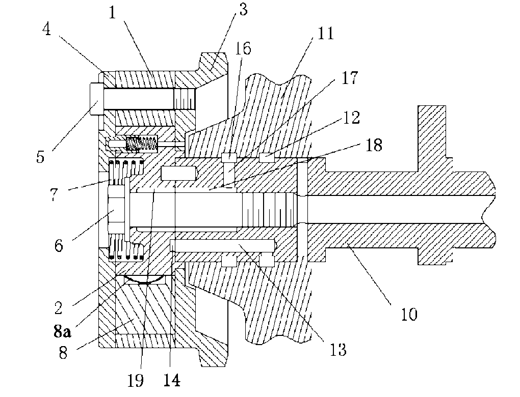
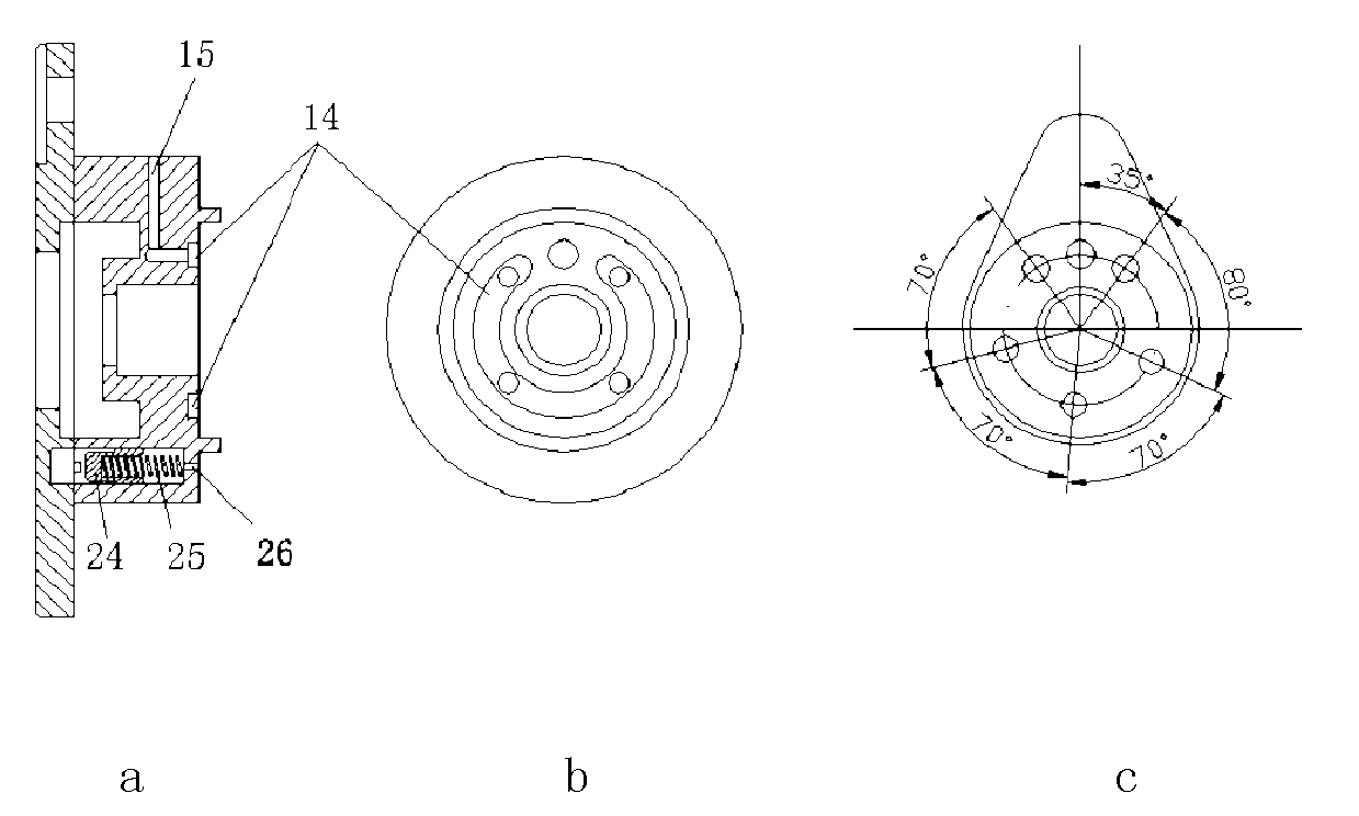
[0016] Such as figure 1 , figure 2 , image 3 As shown, this embodiment includes: housing 1, rotor 2, sprocket 3, front end cover 4, fastening bolt 5, center bolt 6, torsion return spring 7, blade 8, diaphragm spring 8a, advance cavity 9a, delay Cavity 9b, camshaft 10, first lock pin oil passage 21, second lock pin oil passage 22, lock pin 24, lock pin spring 25 and lock pin oil drain hole 26, wherein: rotor 2, cam The shaft 10 is fixed by the central bolt 6, the front cover 4, the housing 1 and the sprocket 3 are fixed by the fastening bolt 5, the blade 8 is fixed around the rotor 2, and there is a diaphragm s...


PUM


Abstract

The present invention relates to a variable valve timing-phase controller, belonging to the field of engine technique. The invention comprises a shell body, a rotor, a chain wheel, a front end cap, a camshaft, a centre bolt, a vane, a diaphragm spring, a torsion return spring, an advance chamber, a delay chamber and a locking mechanism. The rotor and the camshaft are fixedly arranged through the centre bolt, and the front end cap, the shell body and the chain wheel are fixedly arranged through a drawbolt. The vane is fixedly arranged around the rotor, the rotor is connected with the vane through the diaphragm spring to ensure the tight attachment of the vane and the shell body. The torsion return spring is fixedly arranged between the rotor and the front end cap, a lock pin is movably arranged in the rotor, and the advance chamber and the delay chamber are respectively arranged at one side of the rotor opposite to a back end cap and are separated mutually. The invention avoids the elongation of the axial length of the camshaft and provides a very large phase adjustment range by using a symmetrical four-blade structure. The innovative design of an annular oil passage below the rotor solves the matching problem between the phase controller and the existing camshaft.

Description

technical field [0001] The invention relates to a device in the technical field of automobile engines, in particular to a variable valve timing phase controller. Background technique [0002] Engine variable valve timing phase control technology is a technology used in automobile engines to control camshaft phase. The principle of engine variable valve timing phase controller technology is to adjust the phase of the camshaft according to the operating conditions of the engine through the variable valve timing mechanism installed on the engine camshaft, thereby adjusting the amount of intake (exhaust) , and the opening and closing time and angle of the valve, so that the amount of air entering can be optimized and the combustion efficiency can be improved. The advantage is fuel economy while meeting stricter emission requirements. [0003] After searching the prior art, it is found that the US Patent Document No. US4,858,572 records a "phase difference adjustment device". W...

Claims


Application Information

Patent Timeline
Patent Type & Authority Applications(China)
IPC IPC(8): F01L1/344
Inventor 许敏张玉银苏建业朱斌陈晓济
Owner SHANGHAI JIAO TONG UNIV
Why Eureka
Try Eureka