Interconnected line failure detection method

A detection method and interconnection line technology, applied in the direction of measuring electricity, measuring devices, measuring electrical variables, etc., can solve the problems of reduced detection efficiency, destructiveness, complicated process, etc., and achieve improved efficiency, positioning accuracy, and detection speed Fast and easy results

Inactive Publication Date: 2010-07-07
SEMICON MFG INT (SHANGHAI) CORP
View PDF1 Cites 6 Cited by
  • Summary
  • Abstract
  • Description
  • Claims
  • Application Information

AI Technical Summary

Problems solved by technology

[0006] The speed of detecting failed interconnection lines in the existing technology is slow, and the process of determining the location of the

Method used


Image

  • Interconnected line failure detection method
  • Interconnected line failure detection method
  • Interconnected line failure detection method

Examples


Embodiment Construction

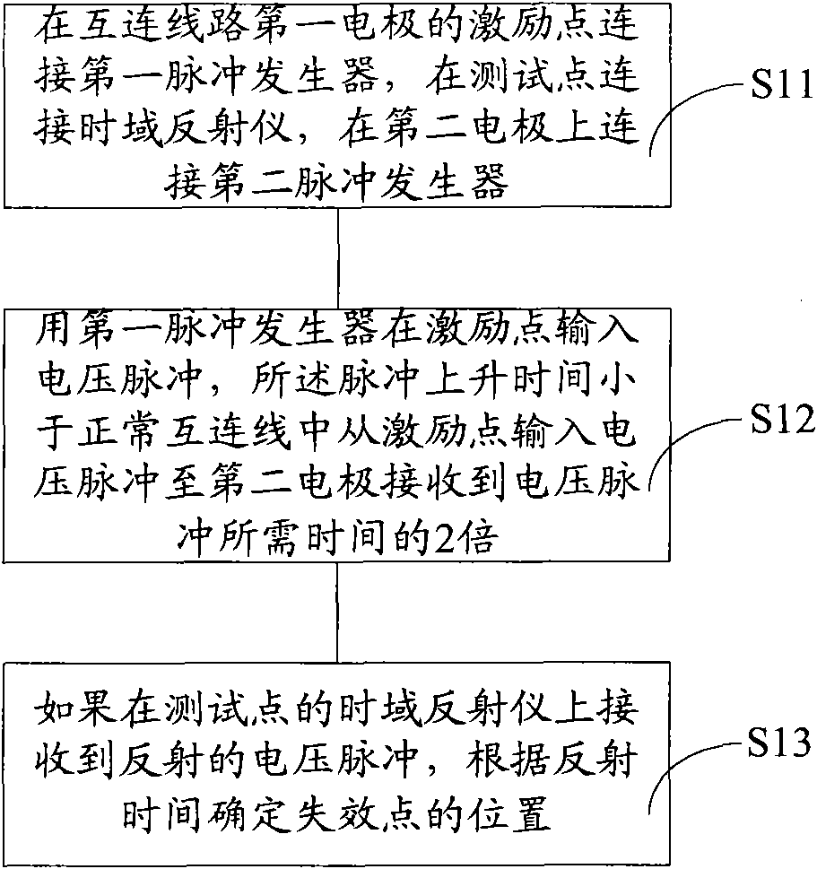
[0022] In the prior art, the failure location is usually determined by cutting the section of the failed semiconductor device with a focused ion beam until the failure point is exposed. The process is complicated and the detection efficiency is low. In the present invention, the excitation point of the first electrode of the interconnect circuit is connected to the first pulse generator, and a voltage pulse is input. If the interconnection is normal, i.e. not open, open or short, a voltage pulse can be received on the second pulse generator at the second electrode of the interconnect; and when the interconnect is open, open or short , the voltage pulse cannot be transmitted to the second pulse generator of the second electrode, and the voltage pulse will be reflected back to the time domain reflectometer at the test point of the first electrode in an open circuit, open circuit or short circuit, and the voltage pulse will be reflected from the launch to the back The time requir...


PUM

PropertyMeasurementUnit
Impedanceaaaaaaaaaa
Lengthaaaaaaaaaa

Abstract

The invention discloses an interconnected line failure detection method, which comprises the following steps: connecting a first pulse generator to an excitation point of a first electrode of an interconnected line; connecting a time-domain reflectometer to a test point; connecting a second pulse generator to a second electrode; inputting a voltage pulse to the excitation point by using the first pulse generator, wherein the raising time of the pulse is 2 times less than the time for inputting the voltage pulse from the excitation point in the interconnected line to receiving the voltage pulse by the second electrode; and determining the position of failure points according to the reflecting time if the reflected voltage pulse is received by the time-domain reflectometer of the test point. The invention improves the speed and the efficiency of the detection and the accuracy of the positioning.

Description

technical field [0001] The invention relates to a failure detection method of an interconnection line, in particular to a failure detection method of a non-destructive semiconductor wafer interconnection line. Background technique [0002] Multilayer interconnection technology has become an important part of the manufacturing process of large-scale integrated circuits and very large-scale integrated circuits. The current high-performance VLSI has as many as 7-8 layers of copper interconnection lines. Therefore, seeking metal interconnection materials with lower resistivity and insulating materials with lower dielectric constant has become a major research direction for deep submicron and nanometer devices. [0003] With the continuous improvement of integrated circuit integration, the metal wiring becomes thinner, narrower, and thinner, so the current density in it becomes larger and larger. Under the effect of higher current density, the metal atoms in the metal wiring wi...

Claims


Application Information

Patent Timeline
IPC IPC(8): G01R31/02G01R31/11H01L21/66
Inventor 王津洲
Owner SEMICON MFG INT (SHANGHAI) CORP
Why Eureka
Try Eureka