Control method for intelligent valve positioner

A control method and intelligent valve technology, applied in the direction of using feedback control, etc., can solve the problems of increasing the work difficulty of on-site operators, prone to human errors, poor adaptability, etc., and achieve simple and fast debugging, convenient debugging and operation, and fast positioning speed Effect

Active Publication Date: 2010-07-07
衡阳北方光电信息技术有限公司
View PDF0 Cites 16 Cited by
  • Summary
  • Abstract
  • Description
  • Claims
  • Application Information

AI Technical Summary

Problems solved by technology

[0003] The adjustment of various control parameters of the existing intelligent valve positioner must be implemented at the installation site, and the debugging is cumbersome, which increases the work difficulty of the on-site operators and is also prone to human errors
Moreover, the e

Method used


Image

  • Control method for intelligent valve positioner
  • Control method for intelligent valve positioner
  • Control method for intelligent valve positioner

Examples


Embodiment Construction

[0036] Such as figure 1 As shown, the controller 901 outputs the setting signal, enters the power supply and signal conditioning module 903 through two wires 902, provides the working power of the whole machine, extracts the control signal and sends it to the MSP430 single-chip microcomputer 906, and the current valve position of the actuator 909 is sent by the valve position sensor 908. to the MSP430 single-chip microcomputer; the adaptive PID control program 904 compares the setting signal with the feedback signal, and after performing adaptive PID processing on the deviation, sends the PWM signal at the next moment, and the I / P conversion unit 907 is driven by the PWM signal, and then pushed through the pneumatic power amplifier The actuator adjusts.

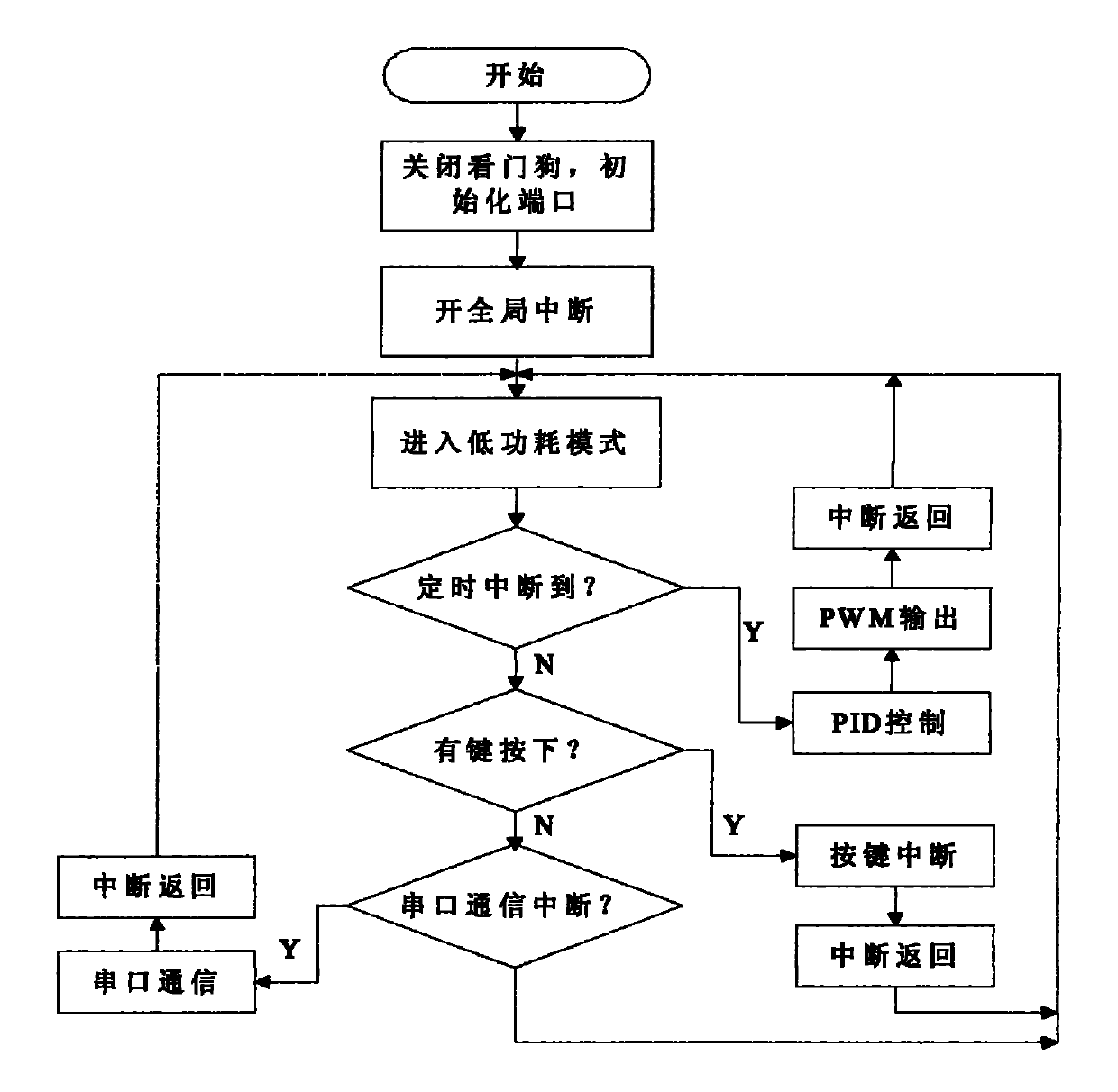
[0037] (1) Main program

[0038] The single chip MSP430 works in low power consumption mode. Its low power consumption is mainly realized by working in idle mode or power-down mode. Except for ACLK activity, the CPU and var...


PUM


Abstract

The invention relates to a control method for an intelligent valve positioner, which has simple and rapid debugging. The technical scheme is that a singlechip receives a set signal sent by a controller and a feedback signal transmitted by a valve position sensor; the set signal is compared with the feedback signal; a bias is subjected to adaptive PID control; a corresponding PWM signal is output to drive an I/P converting unit; and an executing mechanism is driven by a pneumatic power amplifier.

Description

technical field [0001] The invention relates to a control method of an intelligent valve positioner. Background technique [0002] Intelligent valve positioner is a new product popularized and used in the field of automatic control of flow, temperature and pressure. In the field of industrial control, the use of intelligent valve positioner and computer network technology can flexibly form a decentralized or clustered automatic control system, which can improve the efficiency of traditional industries. Automation level and production capacity, thereby improving the economic effect of the enterprise. [0003] The adjustment of various control parameters of the existing intelligent valve positioner must be implemented at the installation site, and the debugging is cumbersome, which increases the work difficulty of the on-site operators and is also prone to human errors. Moreover, the existing smart valve positioners have poor adaptability. For example, pneumatic valves with l...

Claims


Application Information

Patent Timeline
IPC IPC(8): G05D3/12
Inventor 周欢喜王斌慧汪时云
Owner 衡阳北方光电信息技术有限公司
Why Eureka
Try Eureka