
Improvement method for wrinkled copper foil in compacting process of high-rise plates

A pressing process, copper foil technology, applied in the improvement of metal adhesion of insulating substrates, multi-layer circuit manufacturing, printed circuit manufacturing, etc., can solve problems such as increased production costs, inability to symmetrically arrange boards, and reduced production efficiency.

Inactive Publication Date: 2010-07-07
深圳玛斯兰电路科技实业发展有限公司
View PDF6 Cites 11 Cited by
  • Summary
  • Abstract
  • Description
  • Claims
  • Application Information

AI Technical Summary

Problems solved by technology

[0006] Disadvantages: This method can significantly improve the wrinkling of the copper-free area in the actual production process, but it seriously increases the production cost and reduces the production efficiency
[0009] Disadvantages: In addition to the poor quality problems of wrinkling in the non-copper area, high-layer boards also have quality problems such as misalignment between lamination layers, slide plates, and thickness of dielectric layers. Not strong
[0012] Disadvantages: This method can effectively improve the wrinkling of the copper-free area, but for the fully symmetrical inner layer graphics in the copper-free area, the board cannot be symmetrically arranged, and the copper-free area with drilled holes and lines between the choke edge and the graphics, and the outer layer graphics Auxiliary residual copper cannot be added to the area, and the operability is not strong
[0013] From the above methods, it can be known that the original method of improving wrinkling in the copper-free area will not only reduce production efficiency and increase production costs, but also has poor operability

Method used


Image

  • Improvement method for wrinkled copper foil in compacting process of high-rise plates
  • Improvement method for wrinkled copper foil in compacting process of high-rise plates
  • Improvement method for wrinkled copper foil in compacting process of high-rise plates

Examples


Embodiment Construction

[0019] The present invention will be further set forth below by implementing examples and in conjunction with figures, but the following implementing examples should not be interpreted as limitations to the technical solutions of the present invention:

[0020] When making the inner graphic film material (CAM), remove the residual copper on the odd-numbered layers of the blocking side, and only keep the functional targets (such as: pipe hole, rivet hole, alignment PAD, etc.)

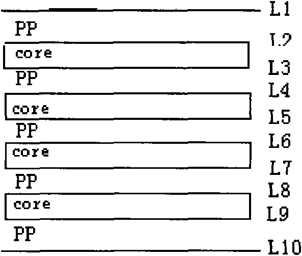
[0021] Taking the 10-layer board as an example, the details are as follows: figure 1 Shown:

[0022] Remove the remaining copper on the choke side of L3, L5, and L7 (except L9) respectively. Boards of other levels are deduced by analogy.

[0023] For boards with an inner core board thickness ≤ 4mil, after removing the flow blocking edge on one side, the board surface will have a large curvature, and the over-etching and browning processes will easily lead to board jamming. Over-etching and browning ca...


PUM


Abstract

The invention discloses an improved method of a wrinkled copper foil in the compacting process of high multi-layer boards, which can improve wrinkling in a copper-free area, and especially improve wrinkling of copper-free sites in a choked flow side and a pattern area. The invention uses the following basic technical scheme: residual copper of the choked flow sides at odd layers are removed and only functional targets are retained when core film data are manufactured; and when the choked flow sides at the board sides are removed from the single face of a board with the inner surface core board thickness equal to or more than 4mil, the board has larger flexibility, and over etching and brown oxide process are easy to cause board blocking. The method for retaining the residual copper at the chocked side corner at the odd layers and using junked thick core boards for adhering and cutting can be used to replace etching and brown oxidizing. The invention has the advantages of ensuring high production efficiency, controlling cost, improving wrinkling in the copper-free area especially wrinkling in the copper-free sites in chocked flow sides and pattern areas, and having stronger operability.

Description

technical field [0001] The invention belongs to the technique for improving wrinkling in a copper-free area of ​​a high-layer board belonging to the field of printed circuit boards. Specifically, the purpose of improving wrinkling in the copper-free area is achieved by optimizing the auxiliary production materials. Background technique [0002] With the rapid development of the electronics industry, printed circuit board technology is developing towards high precision and high multi-layer, and subsequently, higher quality requirements are put forward for the laminated board surface. In the production of high-layer boards in the industry, except for the sundries and pits caused by the sanitation of the production environment, the quality of the board surface is poor. The most common board quality problem is the wrinkling of the copper-free area. The original production process and improvement The process of wrinkling in the copper-free area can no longer meet the requirement...

Claims


Application Information

Patent Timeline
IPC IPC(8): H05K3/00H05K3/38H05K3/46
Inventor 崔宣
Owner 深圳玛斯兰电路科技实业发展有限公司
Learn More