Combined reaction device

A technology of combined reaction and equipment, applied in the field of catalytic reaction equipment, can solve the problems of improving, reducing, fast reaction speed, increasing heat transfer temperature difference ΔT to strengthen heat transfer, etc.

Inactive Publication Date: 2010-07-14
杭州林达化工技术工程有限公司
View PDF0 Cites 19 Cited by
  • Summary
  • Abstract
  • Description
  • Claims
  • Application Information

AI Technical Summary

Problems solved by technology

Aiming at this fundamental contradiction, the present invention breaks through the existing use of coolants at the same temperature, and uses coolants of different temperatures in different sections of the reactor to solve the problem, so that the heat exchange in the reaction can be designed according to the size of the reaction heat removed, which can be specifically determined according to the reaction The flow direction of the gas in the catalyst layer is sequentially divided into multiple blocks before and after, and the coolant is used to exchange heat indirectly through the heat exchange tube. For reactions such as methanol synthesis, where the reaction temperature is within the range of 180°C to 300°C, pressurized heating can be used. Water is used as the heat carrier, and the heat absorbed by the vaporization of the liquid in the reactor is much higher than the sensible heat absorbed by the temperature rise of the cooling medium. For a higher reaction te

Method used


Image

  • Combined reaction device
  • Combined reaction device
  • Combined reaction device

Examples


Embodiment 1

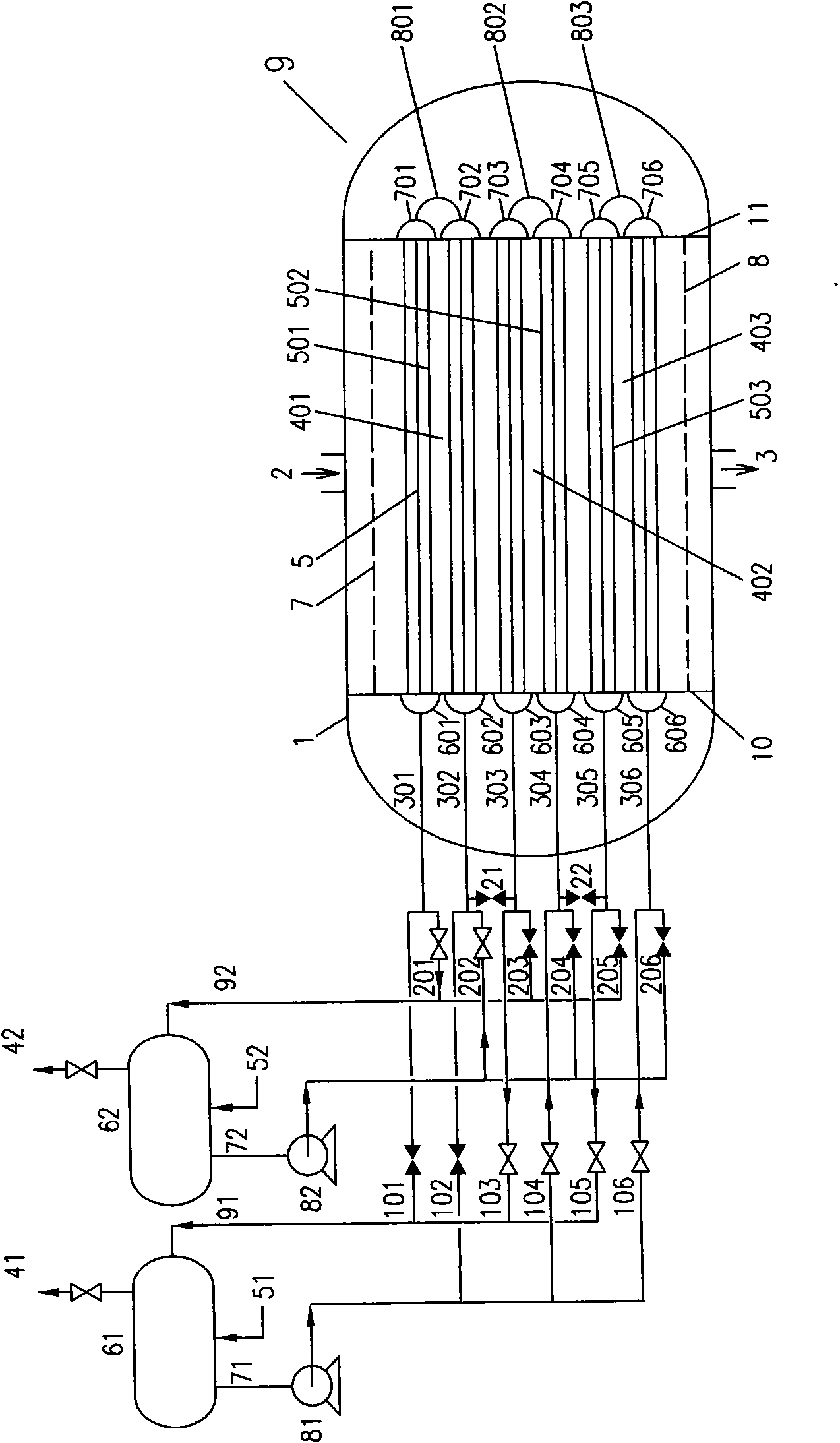
[0022] Embodiment 1: The combined reaction equipment of the present invention is used for methanol synthesis reaction, uses water as cooling medium, adopts image 3 The reaction device 9 shown is connected to steam drums 61,62. image 3 A solid valve means the valve is closed, and a hollow valve means the valve is open. The steam drum 62 connected to the heat exchange tube group 501 can be vaporized at a low pressure of 0.5-3 MPa, and the steam drum 61 connected to the heat exchange tube groups 502 and 503 can be vaporized at a pressure of 1-6 MPa. The reaction gas reacts from top to bottom in the catalyst layer 4, and the upper part has a high reaction speed and a large reaction heat, and can react at a temperature of 230-280°C. The reaction heat of the outer catalyst layer of 503 is small, and the reaction can be carried out at about 220-270°C. It can be seen that the heat transfer temperature difference between the inside and outside of the heat exchange tube group 501 is...

Embodiment 2

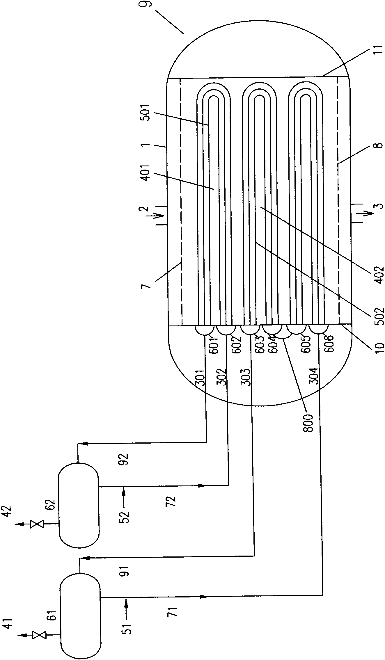
[0027] Embodiment 2: DME is produced with synthetic gas, and the methanol synthesis tower adopts figure 1 Horizontal water-cooling tower with a diameter of 4.0 meters and a built-in NC307 methanol catalyst 120M 3 , methanol dehydration tower to produce dimethyl ether, with a diameter of 3.0 meters and a built-in gamma-alumina methanol dehydration catalyst 50M 3 , the synthesis gas compressed to 9MPa is merged with the recycle gas, heated to 230°C and fed into the methanol synthesis tower, and the methanol synthesis reaction is carried out on the methanol catalyst layer at a temperature of about 250°C. The reaction heat is absorbed by the water in the horizontal water pipe in the synthesis tower to produce steam by-product, and the CH in the methanol synthesis tower gas is released. 3 The OH content is 21%. It is merged with the recovered methanol after rectification of the product dimethyl ether and enters the methanol dehydration reactor for dehydration to generate dimethyl ...


PUM


Abstract

A composite reaction device is characterized in that the reaction device 9 mainly comprises a cylindrical housing 1 with an end socket, a reaction gas inlet 2 and a reaction gas outlet 3 on the housing 1, a catalyst layer 4, a porous gas distributor 7, a porous gas gathering board 8 and a heat exchange tube 5 for exchanging heat of a cooling medium in the catalyst layer 4, is provided with steam drums 61, 62 of vapor pressure adjusting valve 41, 42 so that the amount of the heat exchanged in the reaction is designed according to the size requirement of reaction heat discharging, and is used for strong heat producing reaction processes such as synthesizing methyl alcohol, dimethyl ether, methanation, F-T reaction and H2S oxidation and the like, thereby decreasing the temperature difference, improving the reaction efficiency and the yield, saving the energy, reducing the consumption and realizing large scale purpose.

Description

technical field [0001] The invention is a catalytic reaction equipment, which is used for fluid catalytic reaction and heat transfer process, belongs to the field of chemical engineering, and is especially suitable for strong exothermic reaction processes such as synthesis of methanol, dimethyl ether, methanation, F-T reaction and H2S oxidation. Background technique [0002] For methanol synthesis, synthesis gas to dimethyl ether, methanation, F-T reaction, H 2 For some strong exothermic reactions such as S oxidation, in order to improve the reaction efficiency, the reaction heat needs to be removed at the same time. For example, the Lurgi shell-and-tube methanol tower uses shell-side water to remove the reaction heat in the reaction tube. If Q R Indicates the heat of reaction, Q E Indicates heat transfer to the coolant, when Q R =Q E isothermal reaction, the heat transfer can be expressed as Q E =KFΔT, where K is the heat transfer coefficient, F is the heat transfer are...

Claims


Application Information

Patent Timeline
IPC IPC(8): B01J8/04
Inventor 楼韧楼寿林
Owner 杭州林达化工技术工程有限公司
Why Eureka
Try Eureka