
Calibrating and loading bench of large multi-dimensional force transducer

A multi-dimensional force sensor and loading platform technology, which is applied in the direction of instruments, force/torque/power measuring instrument calibration/testing, and measuring devices, can solve the problems of high labor intensity, high labor intensity, and poor versatility, and achieve reduction The effects of labor intensity, large loading range, and convenient connection and disassembly

Inactive Publication Date: 2010-07-14
YANSHAN UNIV
View PDF3 Cites 55 Cited by
  • Summary
  • Abstract
  • Description
  • Claims
  • Application Information

AI Technical Summary

Problems solved by technology

However, if the above two loading methods are applied to the multi-dimensional calibration force loading of large-scale multi-dimensional force sensors, especially ton-level multi-dimensional force sensors, it will face greater difficulties: during the calibration loading process of large-scale six-dimensional force sensors, it is necessary to move the sensor in 20 directions. Applying a large range of loads, the loading platform designed by the above two methods has a large structural volume, which not only brings greater labor intensity to the on-site calibration experiment personnel, but also basically cannot be achieved for large tonnage force loading, and it is even more difficult to achieve six-dimensional Force transducers apply defined dynamic loads
In order to realize the loading calibration of large-scale multi-dimensional force sensors, some solutions have been proposed at present: such as the patented technology disclosed in Chinese patent CN101226095A, the principle is to use jacks for loading calibration, which solves the problem of large-scale force loading, but cannot be used in the process of force loading calibration. Realize continuous unloading, automatic loading and dynamic calibration
Another loading table that can provide multi-dimensional loading force has been disclosed by Chinese patent CN1727861A. This structure realizes multi-directional loading of the sensor, but there are also problems with the large structure of the loading table, which cannot be automatically loaded and its dynamic load loading, etc. question
Chinese patent ZL200810020512.9 discloses a six-dimensional force sensor calibration device, which is suitable for calibration devices of large-scale six-dimensional force sensors, but it cannot realize continuous unloading during the calibration process. Chinese patent ZL200510050834.4 discloses a stepless lifting six-dimensional force sensor The force sensor calibration device, Chinese patent ZL200510050822.1 discloses a parallel six-dimensional force sensor calibration device. The gantry frame uses ropes and a reducer to apply the load. It has the advantages of simple structure and low manufacturing cost, but it is not easy to implement. Moment and its large tonnage load loading
However, the current calibration loading method basically continues the weight loading method adopted by the small six-dimensional force sensor. The calibration experiment is labor-intensive, and the resolution of the loading calibration force is not high, especially the dynamic loading calibration experiment is more difficult. accomplish
In addition, most of the current multi-dimensional force loading calibration benches are special-purpose, and their versatility is poor. In particular, there are few multi-dimensional force loading calibration devices suitable for large-scale six-dimensional force sensors, especially for dynamic calibration of multi-dimensional force sensors. Devices loaded with force and dynamic loads are even less reported, which brings obstacles to the development of large-scale six-dimensional force sensors with good static and dynamic characteristics.

Method used


Image

  • Calibrating and loading bench of large multi-dimensional force transducer
  • Calibrating and loading bench of large multi-dimensional force transducer
  • Calibrating and loading bench of large multi-dimensional force transducer

Examples


Embodiment Construction

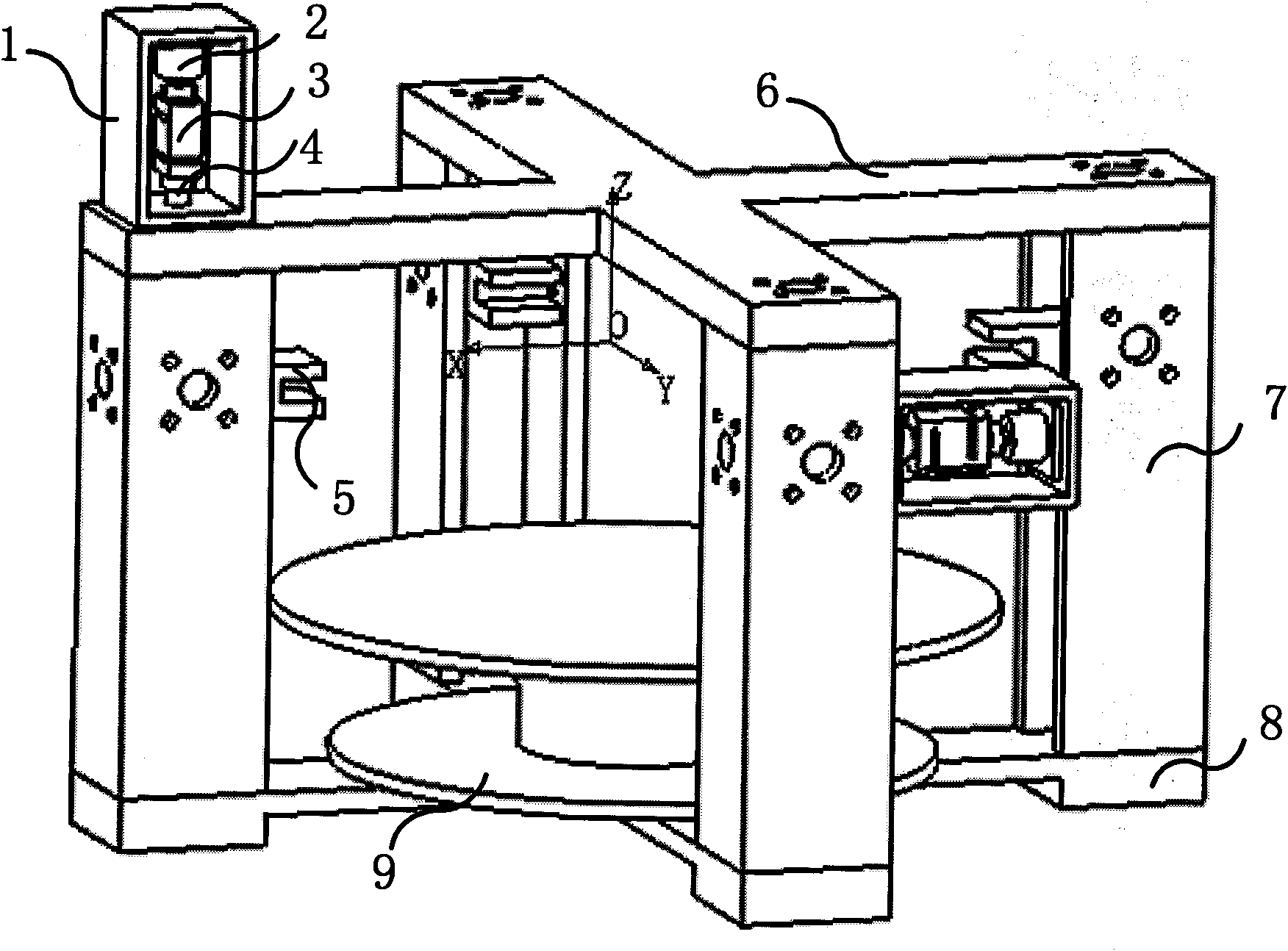
[0015] figure 1 Schematic diagram of the structure of the loading table for large multi-dimensional force sensor calibration, including the upper cross (6), the loading table column (7), the lower cross (8), two loading units and four loading blocks (5), the upper cross (6) It is connected with the lower cross (8) through four loading platform columns (7), and the lower cross (8) is connected with the multi-dimensional force sensor fixed support (9), and the three surfaces of the same height of the loading platform column (7) are provided In the first installation hole for installing the loading unit, the ends of the upper cross (6) and the lower cross (8) are provided with second installation holes for installing the loading unit. The loading frame (1) is installed in the first installation hole of the column (7) of the loading platform.

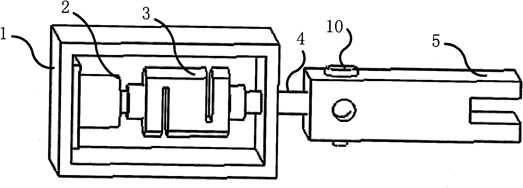
[0016] figure 2 It is a schematic diagram of the connection between the loading unit and the loading block, which consists of a loading...


PUM


Abstract

The invention discloses a calibrating and loading bench of a large multi-dimensional force transducer. The loading bench comprises an upper cross frame (6), a loading bench column (7), a lower cross frame (8), a multi-dimensional force transducer fixed support (9), loading units and loading blocks (5), wherein each loading unit comprises a loading frame (1), a loading hydraulic cylinder (2), a one-dimensional tension-pressure transducer (3) and a tension bar (4). By combining the different installation positions of the two loading units and the connection position of the tension bars (4) and the loading blocks (5), the calibration and the loading of the multi-dimensional force transducer can be realized. Compared with the prior art, the invention has the advantages of simple and compact structure, large range for calibrating and loading the force and high loading accuracy. Besides, by regulating the pressure of a hydraulic system, the invention can easily realize the continuous adjustment of the loaded force and the automatic and dynamic loading of the calibrated force, thereby being especially applicable to the static and dynamic calibration and loading of the large multi-dimensional force transducer.

Description

technical field [0001] The invention relates to the field of a multidimensional force sensor calibration loading table, in particular to a loading device suitable for static and dynamic calibration of large multidimensional force sensors in this field. Background technique [0002] After the processing of the sensor body structure is completed, a loading calibration experiment should be carried out to determine the input-output relationship of the sensor. The loading calibration device occupies a very important position during the development of the sensor, and the level of loading accuracy directly determines the level of sensor measurement accuracy. For single-dimensional force sensors, the loading calibration is generally carried out on the calibration test machine. The loading calibration technology is very complete and mature, and corresponding national standards have been formulated. For multi-dimensional force sensor loading calibration, there is no relatively comple...

Claims


Application Information

Patent Timeline
IPC IPC(8): G01L25/00
Inventor 赵延治赵铁石丁长涛
Owner YANSHAN UNIV
Learn More