
System for measuring linear and non-linear magneto-optical Kerr rotation

A magneto-optical Kerr and measurement system technology, applied in the direction of measuring devices, material analysis through optical means, instruments, etc., can solve the problems of sample test temperature and the size of the magnetic field, and achieve simple structure, convenient adjustment, and signal-to-noise Higher effect

Inactive Publication Date: 2010-07-14
INST OF SEMICONDUCTORS - CHINESE ACAD OF SCI
View PDF0 Cites 20 Cited by
  • Summary
  • Abstract
  • Description
  • Claims
  • Application Information

AI Technical Summary

Problems solved by technology

Usually, the samples are placed on the sample holder, and then they are immersed in the liquid helium Dewar for measurement, so it is difficult to continuously change the test temperature of the sample and the size of the magnetic field

Method used


Image

  • System for measuring linear and non-linear magneto-optical Kerr rotation
  • System for measuring linear and non-linear magneto-optical Kerr rotation
  • System for measuring linear and non-linear magneto-optical Kerr rotation

Examples


Embodiment Construction

[0035] In order to make the objectives, technical solutions, and advantages of the present invention clearer, the following further describes the present invention in detail in conjunction with specific embodiments and with reference to the accompanying drawings.

[0036] The linear and non-linear magneto-optical Kerr measurement system provided by the present invention will be described below through the above drawings.

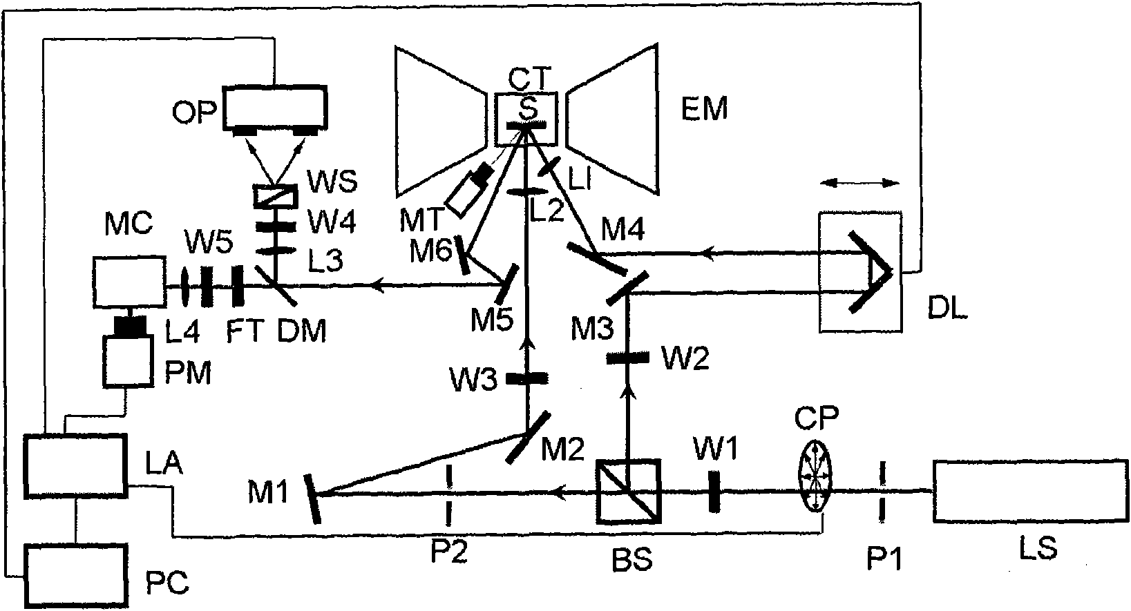
[0037] See figure 1 , figure 1 It is a structural diagram of the linear and nonlinear magneto-optical Kerr measurement system provided by the present invention, which includes:

[0038] A picosecond / femtosecond pulsed laser LS, its output wavelength is continuously adjustable from 680nm to 980nm, the repetition frequency is 76MHz, and the power is 900mW. The outgoing laser is used to pump and detect the linear and nonlinear Kerr signals of the sample S. The laser light emitted by the laser LS is precisely positioned by the two positioning holes P1 and P2, which is...


PUM


Abstract

The invention discloses a system for measuring linear and non-linear magneto-optical Kerr rotation, which comprises an ultra-short pulse laser, a helium-based closed-cycle refrigerator, an electromagnet, a laser-pumping optical path, a laser-detection optical path, a linear Kerr signal collection optical path, a non-linear Kerr signal collection optical path, a lock-in amplifier signal collection system and a laser spot monitoring system, wherein the helium-based closed-cycle refrigerator is provided with optical windows and used for controlling the temperature of a sample; the size of the air gap and the magnitude of the magnetic field of the electromagnet are adjustable; the laser-pumping optical path is used for leading in the laser inputted by the ultra-short pulse laser and focusing the laser on the surface of the sample inside the refrigerating head, so as to excite the sample; the polarization plane of the laser-detection optical path rotates after a beam of laser outputted by the ultra-short pulse laser is reflected by the sample; the linear Kerr signal collection optical path is used for collecting the base-frequency signal of the detection laser; the non-linear Kerr signal collection optical path is used for receiving the frequency-doubled signal of the detection laser; the lock-in amplifier signal collection system is used for filtering and amplifying the signals and transmitting the signals to a computer for processing; and the laser spot monitoring system is used for accurately controlling the overlap ratio of the pumped beam laser spot and the detected beam laser sport. The system provided by the invention for measuring the linear and non-linear magneto-optical Kerr rotation is capable of simultaneously adjusting the temperature and the intensity of the magnetic field applied to the sample and achieving the measurement of the linear and non-linear magneto-optical Kerr effect on a temperature-variable steady-state basis or a time-resolved dynamic basis.

Description

Technical field [0001] The invention relates to a time-resolved linear and nonlinear magneto-optical Kerr measurement system for measuring magnetic metals, semi-metals, semiconductor film materials and low-dimensional quantum structures. Background technique [0002] Semiconductor spintronics has received extensive attention because of its advantages that conventional electronics can’t match. The study of spin polarization and its dynamic evolution is an important part of the basic physics research of spintronics. The experimental research on this problem is mainly realized by time-resolved magneto-optical Kerr rotation technology. The principle is: a beam of linearly polarized laser is incident on the material under study. The magneto-optical effect occurs due to the interaction of the photon and the electron spin magnetic moment of the material, that is, the refractive index of the material changes, resulting in the polarization plane of the reflected laser. Rotate, the rotat...

Claims


Application Information

Patent Timeline
Patent Type & Authority Applications(China)
IPC IPC(8): G01N21/19
Inventor 张新惠朱永刚
Owner INST OF SEMICONDUCTORS - CHINESE ACAD OF SCI
Learn More