Radiating system

A heat dissipation system and heat dissipation device technology, applied in the direction of cooling/ventilation/heating transformation, electrical components, electric solid devices, etc., can solve the problems of reducing the ratio of heat exchange to pump power, maximizing heat exchange and reducing heat exchange economy, etc. Achieve high heat transfer strength

Inactive Publication Date: 2010-07-14
BEIJING JIAOTONG UNIV
View PDF0 Cites 14 Cited by
  • Summary
  • Abstract
  • Description
  • Claims
  • Application Information

AI Technical Summary

Problems solved by technology

The microchannel heat sink structure commonly used at present fails to fully realize the maximum heat tr

Method used


Image

  • Radiating system
  • Radiating system
  • Radiating system

Examples


Embodiment Construction

[0030] The system, local structure and technical details of the present invention will be further described in detail below in conjunction with the accompanying drawings.

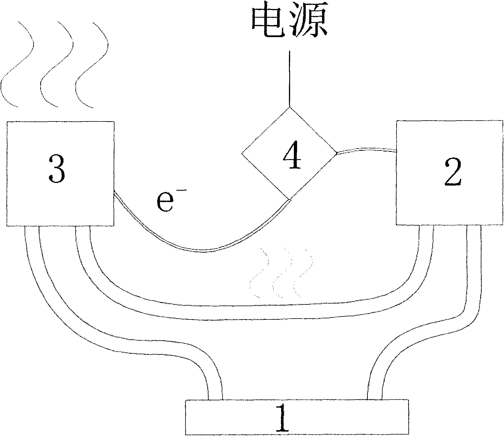
[0031] figure 1 is a schematic diagram of the cooling system of the present invention, as figure 1 As shown, the entire heat dissipation system consists of a microchannel heat sink system 1 , a micropump device 2 , a power supply system 3 and a power supply device 4 to form a self-circulating system. The working fluid cools the heat-generating components in the micro-channel heat sink system 1. The high-temperature working fluid flows out of the micro-channel heat sink system 1 and then enters the power supply system 3. The thermoelectric components made of thermoelectric materials use the temperature difference between the working fluid and the environment to generate electricity. , the auxiliary power supply device 4 provides energy to the micropump device 2, and the driving force of the working fluid in...


PUM


Abstract

The invention discloses a radiating system. The radiating system comprises a microchannel heat-sink system, a micropump device, a power supplying system and a power supply device, wherein the microchannel heat-sink system is used for contacting with a heating part to cool the heating part; the micropump device is connected with the pipeline of the radiating system to consume the electric power provided by the power supply device to provide a circulating power for working fluid in the radiating system; the power supplying system generates additional electric energy by using the afterheat of the working fluid to supply the micropump device; and the power supply device is provided with an additional power supply and a power supply merged by the power supplying system so as to merge the electric energy generated by the power supplying system into the additional power supply and supply power for the micropump device jointly through a series circuit. The radiating device of the radiating system has the advantages of high heat exchange intensity and adaptive characteristic and is applied to the heating parts with small size and high heat-flow density, such as electronic devices, laser devices and the like.

Description

technical field [0001] The invention relates to a heat dissipation device with high heat exchange intensity. Background technique [0002] With the development of science and technology in the direction of miniaturization, great challenges have been posed to the thermal management of systems on a micro scale. In the field of aerospace, with the development of manned spaceflight fields such as space stations, space shuttles and long-distance exploration spacecraft in major countries, the contradiction between the payload of spacecraft and its limited space has become increasingly prominent, which makes the problem of heat dissipation extremely important. Effective geothermal management in a small space has become one of the important indicators to determine the level of a country's manned spaceflight technology. In addition, in the field of semiconductors, with the advancement of MEMS technology, the precision of various electronic devices continues to increase, resulting in...

Claims


Application Information

Patent Timeline
IPC IPC(8): H05K7/20H01L23/46
Inventor 张田田贾力杨立新赵熙科张静茹李星
Owner BEIJING JIAOTONG UNIV
Why Eureka
Try Eureka