Separated drive spindle system of ultraprecision machining tool

An ultra-precision machining and driving technology, applied in the direction of metal processing equipment, etc., can solve the problems of poor power transmission effect and influence on the rotation accuracy of the spindle, and achieve the effect of high rotation, small heating deformation and wide application range

Active Publication Date: 2010-07-21
福建新诺机器人自动化有限公司
View PDF5 Cites 13 Cited by
  • Summary
  • Abstract
  • Description
  • Claims
  • Application Information

AI Technical Summary

Problems solved by technology

[0003] The purpose of the present invention is to solve the problem that in the existing ultra-precision machining equipment, the motor and the main shaft in the main shaft system are rigidly connected, the

Method used


Image

  • Separated drive spindle system of ultraprecision machining tool
  • Separated drive spindle system of ultraprecision machining tool
  • Separated drive spindle system of ultraprecision machining tool

Examples


specific Embodiment approach 1

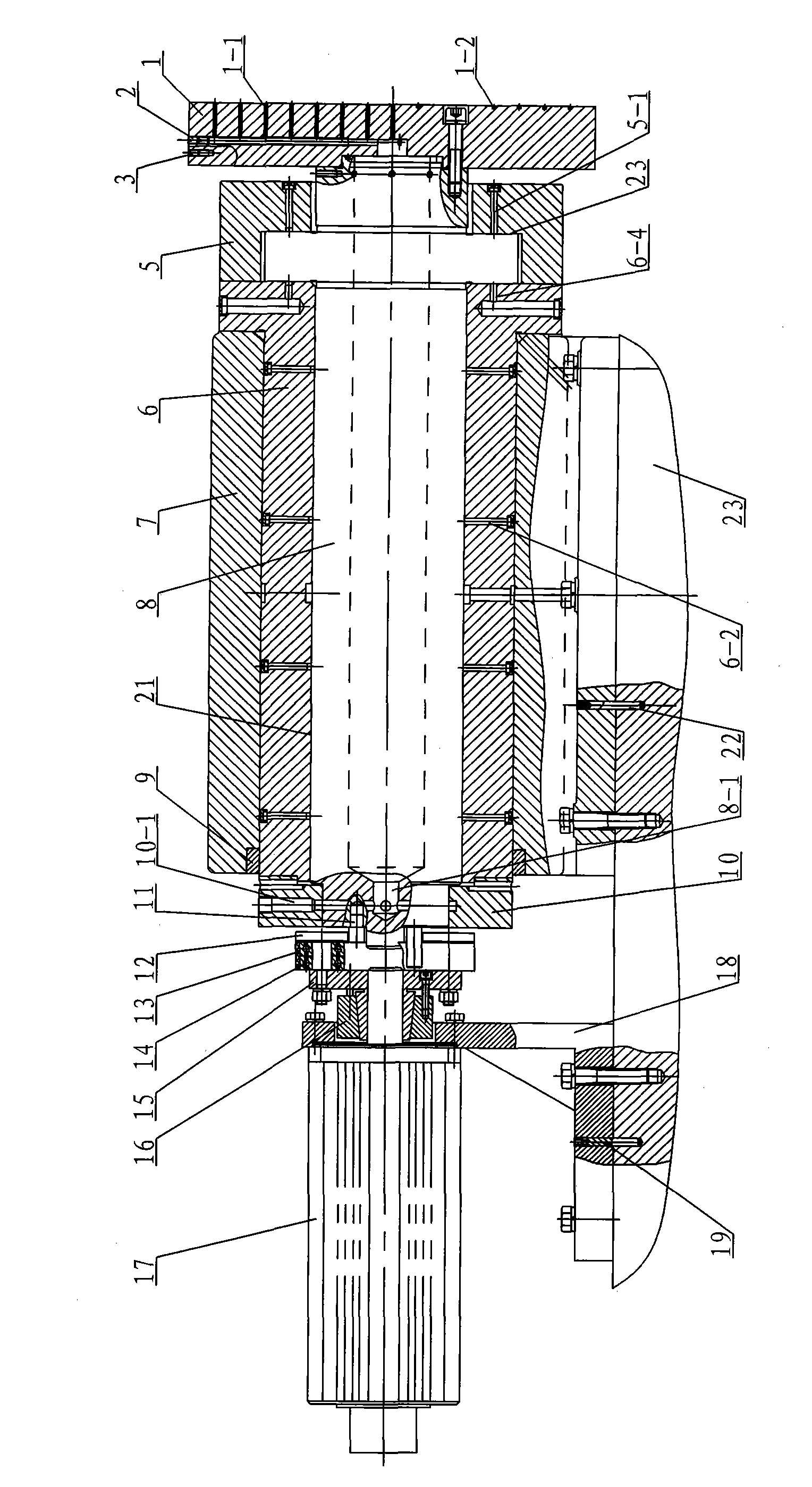
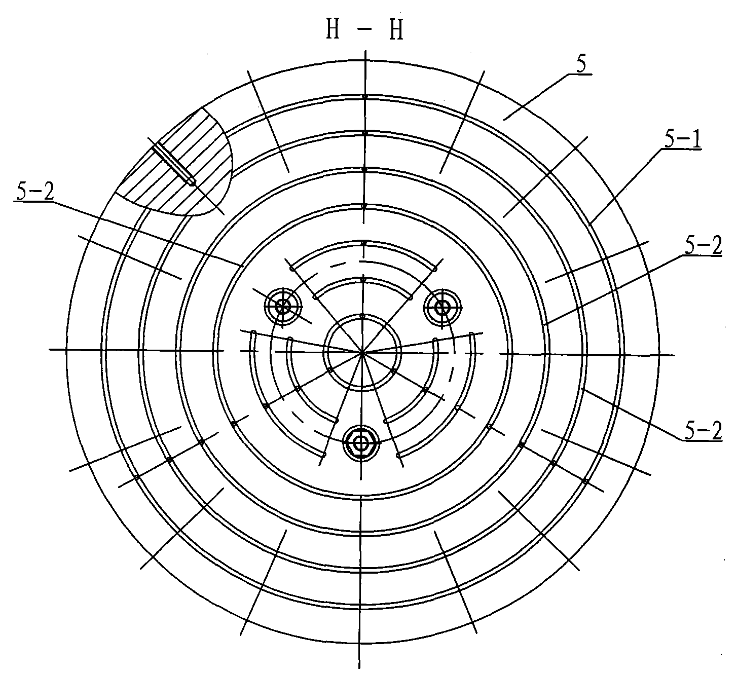
[0007] Specific implementation mode one: combine Figure 1 ~ Figure 4 Describe this embodiment, this embodiment includes an AC servo motor 17, a motor base 18, a first positioning pin 19, a second positioning pin 22, a sliding plate 23, a static pressure gas spindle assembly, a flexible drive assembly and two levers 11, The static pressure gas spindle assembly is composed of air suction cup 1, thrust bearing 5, radial bearing 6, spindle box 7, spindle 8, support ring 9 and gas distribution ring 10, the spindle 8 is installed in the inner hole of the radial bearing 6, There is a radial air film gap 21 between the inner diameter of the radial bearing 6 and the outer diameter of the main shaft 8, the radial bearing 6 is fixed in the main shaft box 7, the main shaft box 7 is connected with the sliding plate 23, and the second positioning pin 22 for positioning, the thrust bearing 5 is set on the output end of the main shaft 8, the thrust bearing 5 and the shaft shoulder end surfac...

specific Embodiment approach 2

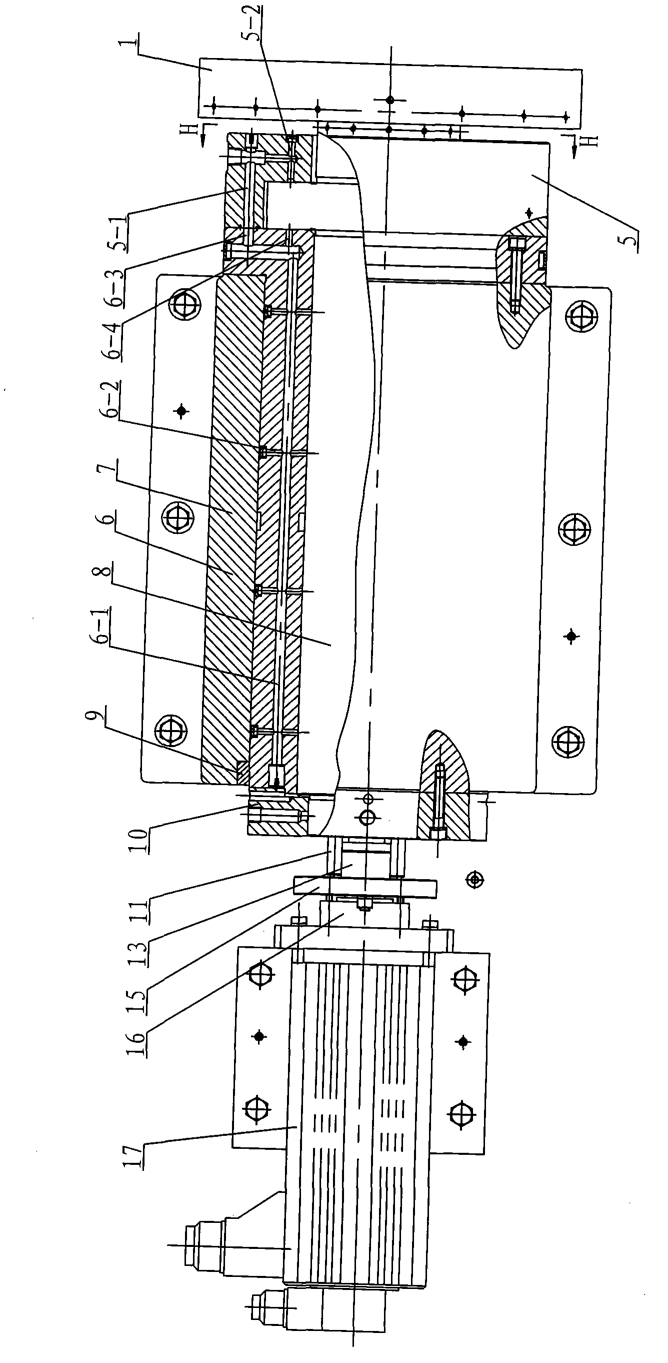
[0008] Specific implementation mode two: combination figure 1 and figure 2 This embodiment is described. The difference between this embodiment and the first embodiment is that it also adds a support ring 9, which is arranged at the connection between the input end of the spindle box 7 and the radial bearing 6. This design is easy to install. Other components and connections are the same as those in the first embodiment.

[0009] Working principle: After the AC servo motor 17 is energized, the AC servo motor 17 starts to rotate, driving the flexible drive assembly to rotate, and the flat belt 13 rotates to drive the lever 11 to generate a rotational torque to drive the spindle 8 to rotate for cutting. The high-pressure air enters through the axial inlet hole 6-1, and after throttling through the radial throttle hole 6-2, a radial gas static pressure film is formed at the radial gas film gap 21, and the radial gas static pressure film supports The main shaft 8 and its radia...


PUM


Abstract

The invention relates to a separated drive spindle system of ultraprecision machining tool, relating to a ultraprecision gas static pressure spindle system. The invention is designed for solving the problem in the existing ultraprecision machining tool that an electric motor and the spindle of the spindle system are in rigid connection, power transmission effect is poor and the rigid connection affects gyration precision of the spindle. After being electrified, an AC servo motor starts to rotate and drives a flexible drive assembly to rotate; a flat belt rotates to drive a driving lever to produce torque to drive the spindle to rotate for carrying out cutting. High pressure air gets in through a radial air inlet hole, is throttled through a radial small throttling hole and forms a radial gas static pressure film at the gap of the radial gas film; the radial gas static pressure film supports the spindle and radial load thereof; high pressure air is throttled through a first axial small throttling hole and then forms an axial gas static pressure film at the gap of an axial gas film, the axial gas static pressure film supports the spindle and axial load thereof. The invention is applied to ultraprecision machining tools and milling machines with various forms.

Description

technical field [0001] The invention relates to an ultra-precision gas static pressure spindle system, in particular to an ultra-precision gas static pressure spindle system with separate flexible connection. Background technique [0002] With the development of science and technology, the development of cutting-edge technologies such as national defense industry and microelectronics industry requires precision and ultra-precision machining equipment and technology, especially ultra-precision machining machine tools, which are the core and key of ultra-precision machining technology. The spindle system of the ultra-precision machining machine tool is the key component of the ultra-precision machining machine tool, and its precision directly affects the machining accuracy of the parts. Therefore, how to design and manufacture ultra-precision spindles has become the core and key of ultra-precision machining machine tools. The design of the spindle of an ultra-precision machin...

Claims


Application Information

Patent Timeline
IPC IPC(8): B23B19/02
Inventor 梁迎春张景和孙雅洲刘海涛
Owner 福建新诺机器人自动化有限公司
Why Eureka
Try Eureka