
Lifting mechanism stroke control device, lifting machine and corresponding control method

A stroke control and hoist technology, applied in sequence/logic controller program control, electrical program control, elevator and other directions, can solve problems such as incorrect calculation of the stroke of the hoisting trolley, errors in the calculation of the stroke of the trolley, and endangering the safety of the hoisting trolley. , to solve the contradiction between running speed and accurate parking, improve running speed, and achieve the effect of precise positioning

Inactive Publication Date: 2010-07-21
SANY HEAVY IND CO LTD (CN)
View PDF0 Cites 15 Cited by
  • Summary
  • Abstract
  • Description
  • Claims
  • Application Information

AI Technical Summary

Problems solved by technology

This stroke control method will be affected by the diameter of the drive wheel of the hoist. When the hoisting cable is wound repeatedly on the drive wheel of the hoist, the winding radius changes, and errors will occur in the stroke calculation of the trolley. In addition, if the signal of the rotary encoder is interfered by the outside, it is easy to If the encoding count is lost or wrong, it will directly lead to an error in the calculation of the lifting trolley stroke; if the rotary encoder fails, the encoding count will be lost directly, and the control system cannot calculate the exact stroke of the lifting trolley, which will endanger the safety of the lifting trolley

Method used


Image

  • Lifting mechanism stroke control device, lifting machine and corresponding control method
  • Lifting mechanism stroke control device, lifting machine and corresponding control method
  • Lifting mechanism stroke control device, lifting machine and corresponding control method

Examples


Embodiment Construction

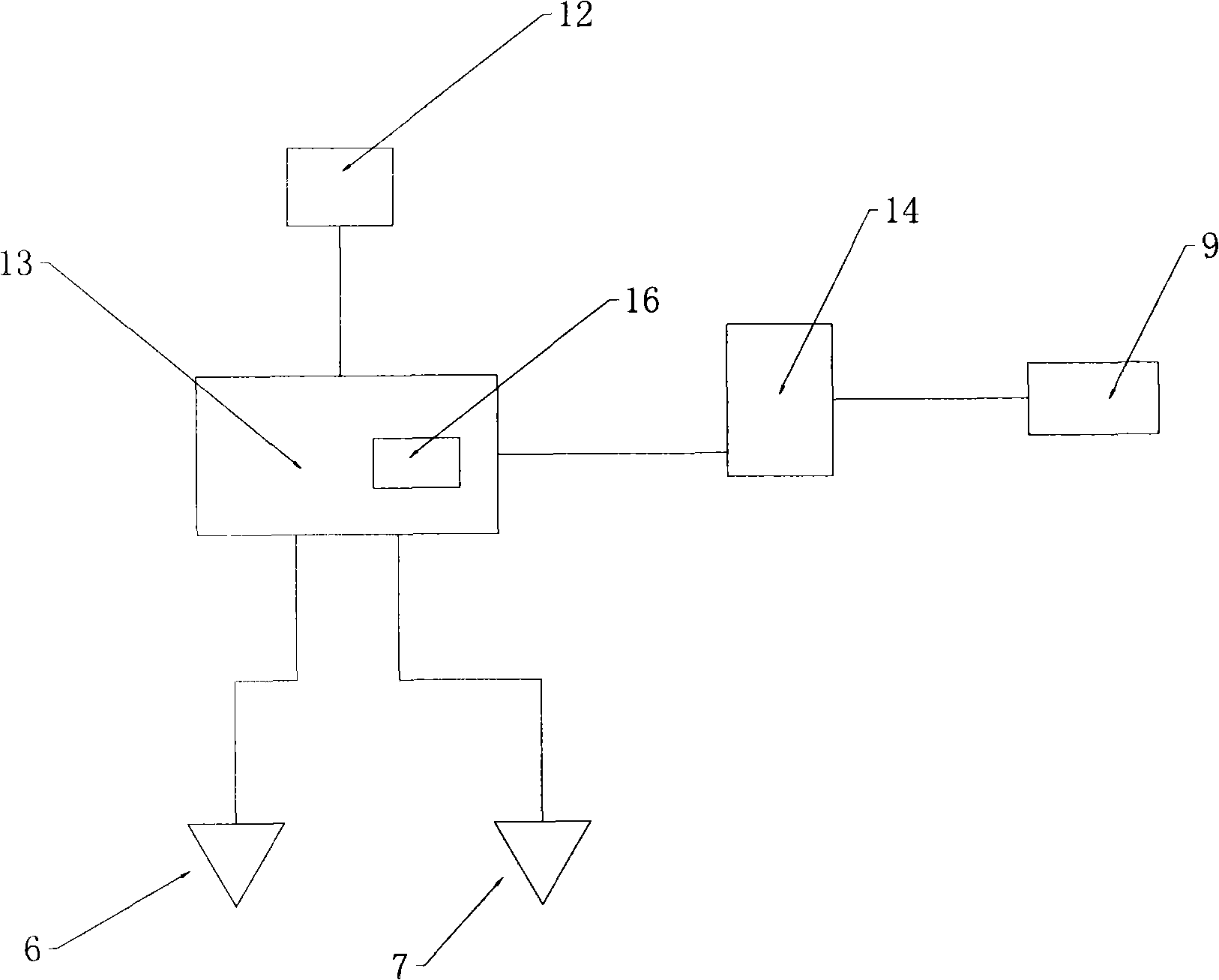
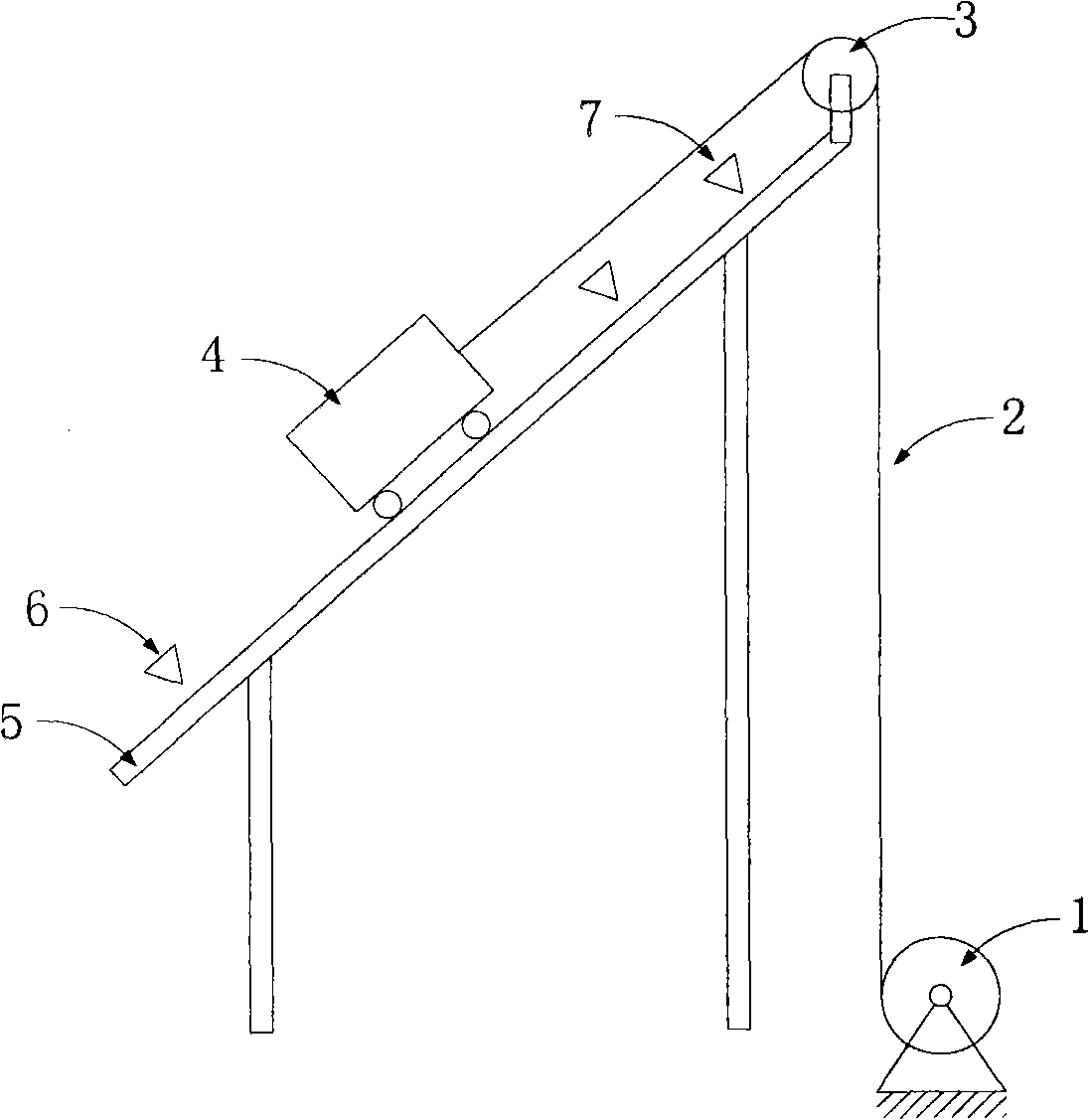
[0025] Such as figure 1 As shown, the hoist stroke control device according to the present invention has: a first detection switch 6, a second detection switch 7, a timer 16, an encoder 12, and a controller 13, wherein the controller 13 receives data from the first detection switch 6 The first position signal, the second position signal from the second detection switch 7, the timing signal from the timer 16 and the count signal from the encoder 13. Meanwhile, the controller 13 is connected with the frequency converter 14 again. Wherein, the frequency converter 14 drives the hoisting motor 9 that is used as the driving device in the present invention, so that the hoisting motor 9 can run at different speeds set under the control of the frequency converter 14, thereby realizing the operation of different speeds. Purpose.

[0026] exist figure 2 A schematic diagram of a hoist according to the invention is schematically shown in . see figure 1 , the hoist of the present inve...


PUM


Abstract

The invention discloses a lifting mechanism stroke control device, which is provided with a first detection switch (6), a second detection switch (7), a coder (12), a timer and a controller (13), wherein the first detection switch (6) is arranged at a starting position and sends a first position signal; the second detection switch (7) is arranged at a stop position and sends a second position signal; the coder (12) sends a counting signal according to the revolution of a driving device; the timer counts operating time and sends a timing signal; the controller (13) receives the signals, and controls the timer to time, the coder to count and the driving device to run at a high speed when receiving the first position signal; the controller compares the timing signal with a preset timing threshold and compares the counting signal with a preset counting threshold in real time; when any one of signal values exceeds the preset threshold, the controller controls the driving device to reduce speed; when not receiving the first position signal, the controller controls the driving device to run at a low speed; and when receiving the second position signal, the controller controls the drivingdevice to stop. The invention also relates to a lifting machine and a method for controlling the control device.

Description

technical field [0001] The invention relates to a stroke control device of a lifting mechanism and a hoist with the control device. At the same time, the invention also relates to a method for controlling such a stroke control device. Background technique [0002] In the construction machinery industry, lifting devices are used in many places to lift heavy objects to high places. Especially in asphalt concrete, cement concrete production and other industries, the production raw materials must be raised to a certain height in order to complete the entire production process through subsequent processes. [0003] At present, judging from the lifting mechanisms used in the construction machinery industry, the lifting mechanisms mainly include continuous type and intermittent type. The continuous lifting mechanism generally lifts the material to a high place through the cyclic action of the lifting mechanism. Common lifting mechanisms of this type mainly include inclined belts...

Claims


Application Information

Patent Timeline
Patent Type & Authority Applications(China)
IPC IPC(8): B66B1/36G05B19/04
Inventor 王征彭贤武赵继成
Owner SANY HEAVY IND CO LTD (CN)
Learn More