Blast-furnace coal powder injection method and system thereof

A pulverized coal injection and blast furnace technology, applied in blast furnaces, blast furnace details, furnaces, etc., can solve the problems affecting the safe and stable operation of the pulverized coal bunker weighing system, the blast furnace pulverized coal injection system, the impact of the pressure relief pipeline system, and the instantaneous pressure relief gas Large volume and other problems, to achieve the effect of reducing the impact, reducing the pressure relief pressure difference, and reducing the pressure relief gas volume

Active Publication Date: 2010-07-21
CISDI ENG CO LTD
View PDF0 Cites 13 Cited by
  • Summary
  • Abstract
  • Description
  • Claims
  • Application Information

AI Technical Summary

Problems solved by technology

The pressurization needs to be carried out by receiving process nitrogen from the factory, and the nitrogen in the pressure relief process is directly discharged into the coal powder bin after the high-pressure gas in the tank is decompressed through the pressure reducing valve without comprehensive utilization, which is a big waste of nitrogen. , increased production costs
In addition, the high pressure difference in the pressure relief process also has a great impact on the pressure relief pipeline system. The instantaneous pressure relief gas volume is large, which affects the weighing system of the pulverized coal bunker and other shortcomings. It has always been a hidden danger for the safe and stable operation of the pulverized coal injection system of the blast furnace.

Method used


Image

  • Blast-furnace coal powder injection method and system thereof
  • Blast-furnace coal powder injection method and system thereof

Examples


Embodiment Construction

[0019] In order to further illustrate the technical means and effects adopted by the present invention to achieve the intended purpose of the invention, the present invention will be further described below with reference to the accompanying drawings and embodiments. The description of the specific implementation manners can provide a detailed description of the technical aspects and effects adopted by the present invention. A deeper understanding, but the present invention is not limited to this.

[0020] The factory-supplied process gas selected in the following embodiments is nitrogen, of course, other suitable gases can also be selected.

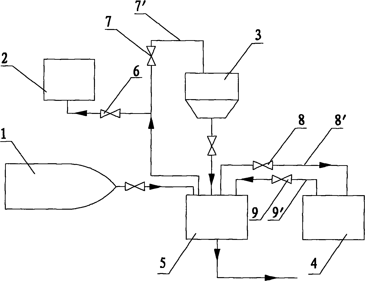
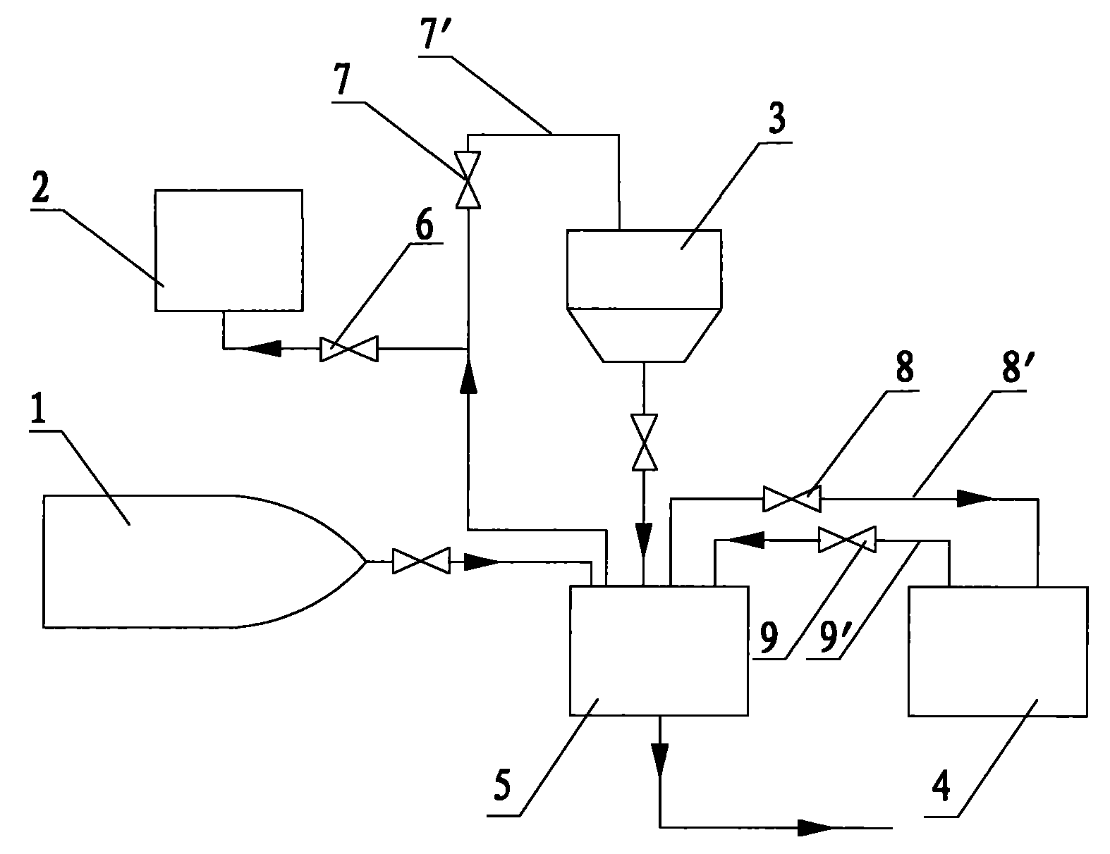
[0021] A blast furnace coal powder injection method, the method includes the following steps:

[0022] Place the pulverized coal in the pulverized coal silo in the injection tank in the injection tank group; connect the injection tank with the gas storage tank. Use the high-pressure gas obtained from the gas supply system of the plant to press...


PUM


Abstract

The invention discloses a blast-furnace coal powder injection method and a system thereof. The method comprises the following steps: A, arranging coal powder stored in a coal powder bin in an injecting tank of an injecting tank group; B, pressurizing the injecting tank by using the high pressure gas obtained from a factory-supplied gas system, and injecting the coal powder into a blast furnace; and C, depressurizing the high pressure gas in the injecting tank, and then directly discharging into the coal powder bin, wherein a step C' needs to be done before the step C, and a step B' needs to be done before the step B. The step C' comprises the following steps: communicating the injecting tank with a gas container, and depressurizing the gas container by using the injecting tank. The step B' comprises the following steps: communicating the injecting tank with the gas container, and pressurizing the injecting tank by using the gas container. The invention can realize the effective recycle of the gas depressurized by the injecting tank, reduce the gas consumption of the powder making and injecting system, save the production cost, reduce the depressurized pressure difference of the depressurization system, decrease the maximum instant depressurized gas flow, reduce the impact on pipelines in the depressurization process, improve the operation stability of the system, and achieve high gas recovery rate.

Description

Technical field [0001] The invention relates to a blast furnace coal powder injection process and its system. Background technique [0002] In the current blast furnace pulverized coal injection process system, high-pressure nitrogen is used to transport pulverized coal. The nitrogen pressure for injection is high and the demand is large. The pulverized coal injection process is "powder loading-pressurization-injection-pressure relief -" The cyclical work of "filling powder" involves the two processes of pressurization and depressurization in each cycle. The pressurization needs to be connected to the factory for process nitrogen, and the nitrogen in the pressure relief process is not comprehensively utilized. The high-pressure gas in the tank is directly discharged into the pulverized coal silo after being decompressed through the pressure reducing valve, which is a big waste of nitrogen. , Increased production costs. In addition, the high pressure difference in the pressure r...

Claims


Application Information

Patent Timeline
Patent Type & Authority Applications(China)
IPC IPC(8): C21B5/00
Inventor 牛立祥颜新王贤吴波张杰肖卫锋
Owner CISDI ENG CO LTD
Why Eureka
Try Eureka