Eureka AIR delivers breakthrough ideas for toughest innovation challenges, trusted by R&D personnel around the world.

Wet spinning device applying regulable magnetic field and method

A technology of wet spinning and spinning device, which is applied in the field of wet spinning device with adjustable magnetic field

Inactive Publication Date: 2010-07-21
SHANGHAI UNIV
View PDF0 Cites 9 Cited by
  • Summary
  • Abstract
  • Description
  • Claims
  • Application Information

AI Technical Summary

Problems solved by technology

Applying an auxiliary magnetic field to the polymer in the wet spinning process to induce the aggregation structure of the spinning solution, macromolecular streams and fibers to achieve performance improvement has not been reported yet.

Method used

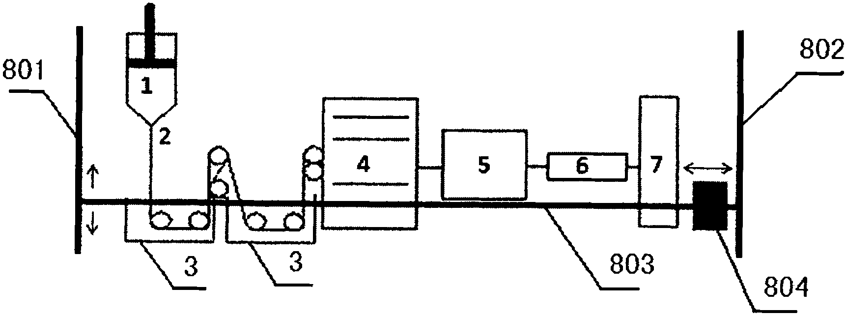

Image

  • Wet spinning device applying regulable magnetic field and method
  • Wet spinning device applying regulable magnetic field and method
  • Wet spinning device applying regulable magnetic field and method

Examples


Embodiment 1

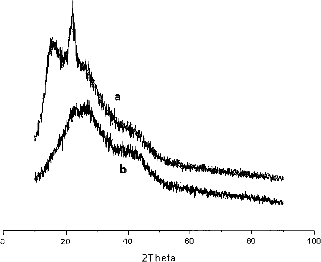
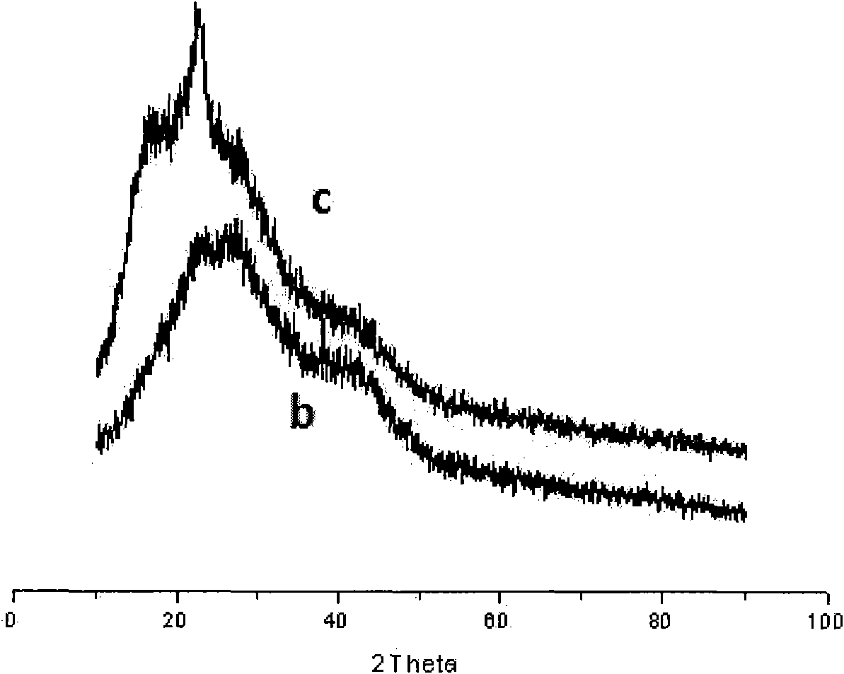
[0023] Embodiment 1: A certain amount of PSA-DMF spinning stock solution with a concentration of 16% is placed in the polymer delivery mechanism 1 for degassing. The coagulation bath 3 sets vertically, the coagulation bath is a mixed solution of DMF and water, the temperature of the coagulation bath is 45°C, and the concentration of DMF is 52%. The cured fibers enter the washing tank 4, the solvent DMF is removed, and the washed fibers enter the drying process. The box 5 is dried, and the temperature of the drying box is set at 160°C to remove residual solvent and water. The dried fibers are stretched through the drafting device 6, and the drafting temperature is set at 270°C, and finally collected by the winding shaft Finished fiber, the rotation speed of the winding shaft is set to 2m / min. The crystallization properties of the obtained fibers are shown in figure 2 (b) and image 3 (b).

Embodiment 2

[0024] Embodiment 2: This embodiment is basically the same as Embodiment 1, the difference is that the adjustment magnetic field generator 804 is placed at the coagulation bath 3 . The magnetic field intensity measured with a magnetometer is 0.5T, and the crystallinity of the fiber obtained is shown in figure 2 (a).

Embodiment 3

[0025] Embodiment 3: This embodiment is basically the same as Embodiment 2, the difference is that the magnetic field generator 804 is adjusted at the drafting device 6 . The magnetic field intensity measured with a magnetometer is 0.5T, and the crystallinity of the fiber obtained is shown in image 3 (c).

[0026] Through the above experimental comparison of polysulfone amide wet spinning with and without magnetic field, combined with figure 2 and image 3 , it can be found that, compared with the traditional wet spinning device, the crystallization property of the fiber obtained by using the wet spinning device of the present invention is obviously improved. It is found by calculation that compared with the fiber obtained in Example 1, the crystallinity of the fiber obtained in Example 2 and Example 3 is increased by 34.2% and 25.7% respectively. The above description of the examples is to facilitate those of ordinary skill in the art to understand and apply the present ...


PUM


Abstract

The invention relates to a wet spinning device applying regulable magnetic field and method, and a method thereof. The device comprises a wet spinning device and a controllable magnetic field generation device. The device is characterized in that: a pair of brackets in the controllable magnetic field generation device is arranged on the two sides of the spinning device respectively; and each bracket has a structure that: a third copper rod capable of moving up and down is horizontally arranged between a first copper rod and a second copper rod which are arranged in parallel; and a magnetic field generator horizontally slides on the third copper rod so as to ensure the application of the magnetic field to different spinning lines. A novel concept in the device and the method is that the regulable magnetic field is applied in sections in the whole spinning process from the preparation of a spinning stock solution to the package and collection of fibers, so that the reconstruction of an aggregative structure of a polymer is realized and the orientation and crystallization of the polymer are improved.

Description

technical field [0001] The invention relates to a wet spinning device and a method thereof, in particular to a wet spinning device and a method for applying a controllable magnetic field. Background technique [0002] With the rapid development of science and technology today, people have higher and higher requirements for material properties. How to obtain high-performance fibers through traditional spinning devices has gradually become a research hotspot. At present, researchers mainly use two ways to improve the performance of fibers: one is to improve the spinning process through the design of the spinning device, and then realize the optimization of the fiber aggregate structure and improve the performance; the other way is to improve the performance of the fiber spinning solution. Modified to improve performance. The performance of the fiber not only depends on the structure of the spinning solution itself, but also is closely related to the spinning process. Magneti...

Claims


Application Information

Patent Timeline
Patent Type & Authority Applications(China)
IPC IPC(8): D01D5/06D01D10/00
Inventor 刘丽顾巍巍吴文潭
Owner SHANGHAI UNIV
Why Eureka
Eureka Blog
Learn More