Device for eliminating wall surface coating

A technology for removing devices and coatings, applied in construction and building construction, etc., can solve the problems of loose overall structure, damage to the surface of the wall, and no collection of dust and debris, so as to improve the clean environment, reduce the work intensity, The effect of ideal balance

Inactive Publication Date: 2010-07-21
CHANGSHU INSTITUTE OF TECHNOLOGY
View PDF1 Cites 7 Cited by
  • Summary
  • Abstract
  • Description
  • Claims
  • Application Information

AI Technical Summary

Problems solved by technology

[0005] The above-mentioned patent scheme has the advantages of reducing labor intensity and improving work efficiency in terms of its practical use, that is, it can make up for the third of the shortcomings mentioned by the applicant above, but the remaining four shortcomings mentioned by the applicant cannot be solved. eliminate
As far as its structure is concerned, there are the following deficiencies: one, because the motor and the casing (the patent is called a cylindrical casing) are arranged in the axial direction, that is, the motor is connected to one end of the casing and is located outside the casing, so the overall structure It is loose and bulky; the second is that it is very troublesome to replace the hammer head. When the hammer head is damaged and replaced, it is necessary to remove the casing from the central shaft first, then take the hammer frame out of the casing, and then remove the hammer shaft from the hammer Finally, remove the hammer head to be replaced from the hammer shaft, and restore the installation according to the above-mentioned reverse process after replacement; the third is that the balance effect is poor, and there is an imbalance phenomenon that one end is heavy and the other end is light. figure 1 According to the description on pages 2 and 3 of the manual, since the motor equipped with the left handle is located at the left end of the case, and the right handle is connected to the right end of the case, the weight difference between the two ends of the case is very different. The force acting on the left handle needs to be several times that of the right handle, which is very prone to fatigue and affects the improvement of work efficiency; fourth, because the motor is external, it is not only poor in safety, but also has a high probability of damage; fifth, it does not have a collection The function of hammering the fallen dust and debris is difficult to guarantee the environment of the job site; six is ​​because of the hammering construction, which is seriously destructive to the surface of the wall, especially not enough to reflect the overall removal of the wall coating , the patent has the situation of focusing on one thing and losing another. The so-called focusing on this means paying attention to the combination effect between the new coating or other materials and the original coating or original materials. The so-called losing the other is to give subsequent coatings or materials Buried the hidden danger of easy falling off in the future, because as mentioned above, the surface structure of the wall is loosened or even destroyed when hammering
[0006] Throughout the above-mentioned patented technology, it is not suitable for the removal of wall coatings. For this reason, the applicant has conceived a technical solution suitable for removing wall coatings after long-term exploration and practice. The content to be introduced below It is against this background that the

Method used


Image

  • Device for eliminating wall surface coating
  • Device for eliminating wall surface coating
  • Device for eliminating wall surface coating

Examples


Embodiment

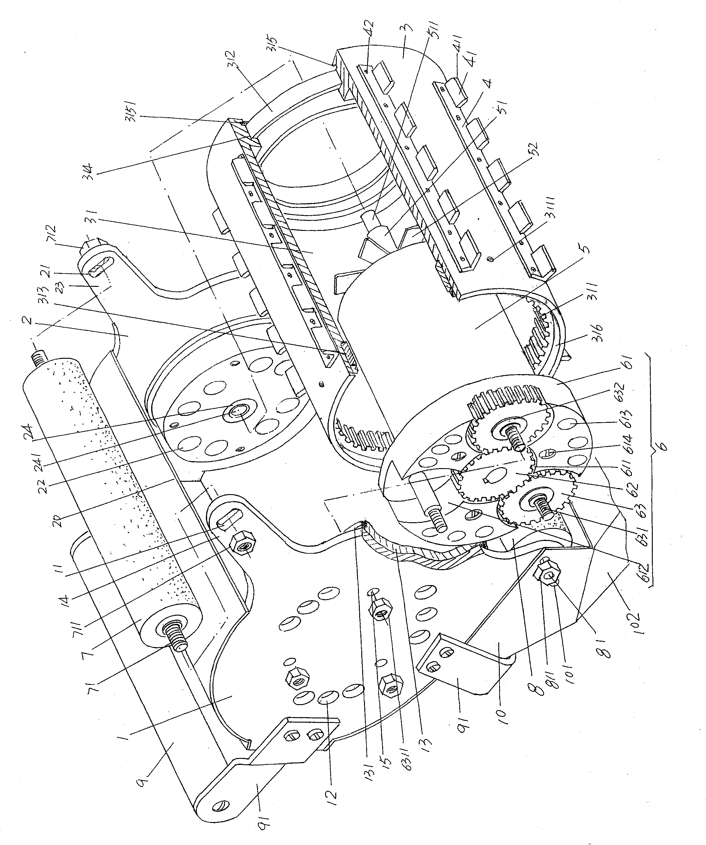
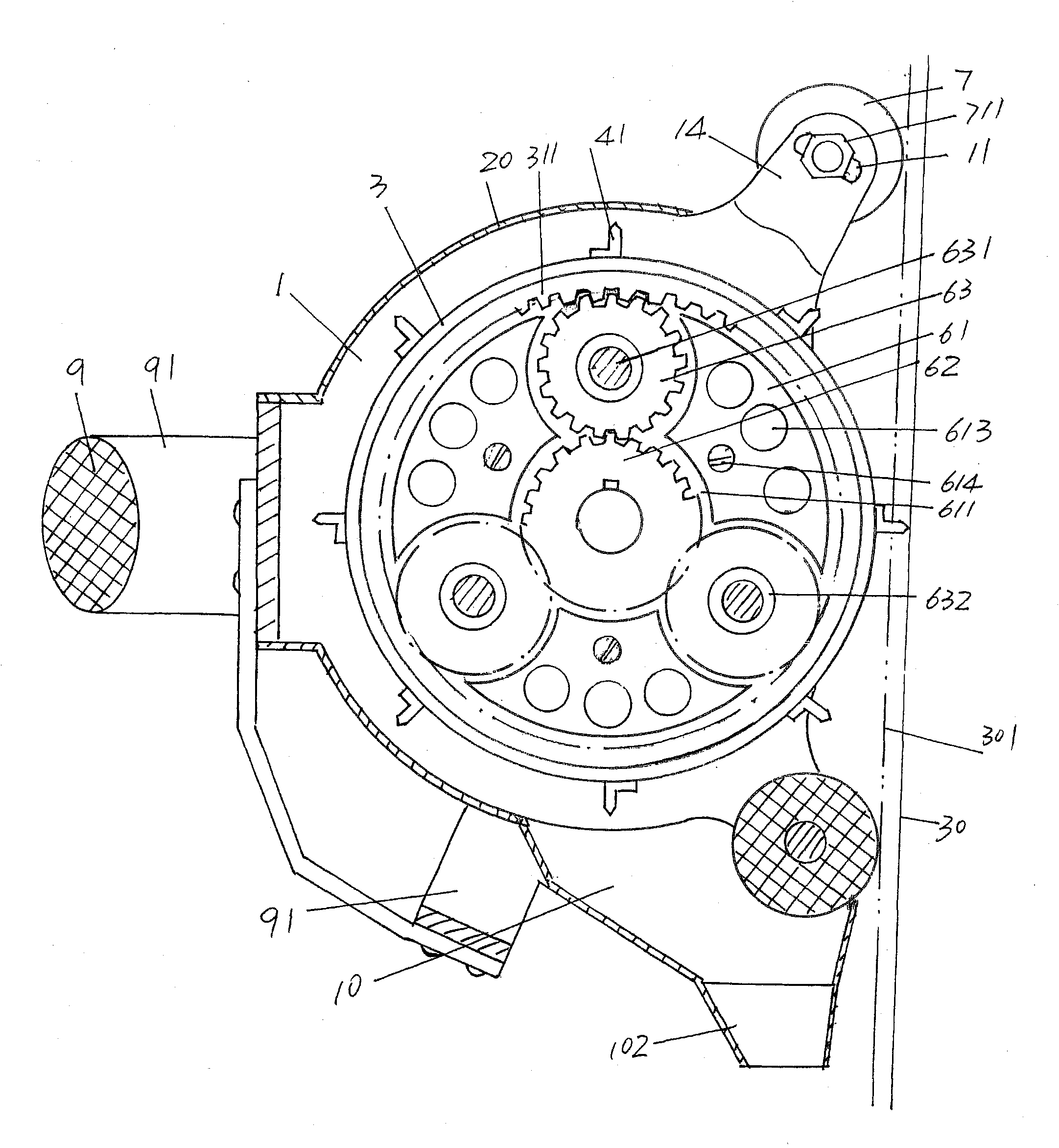
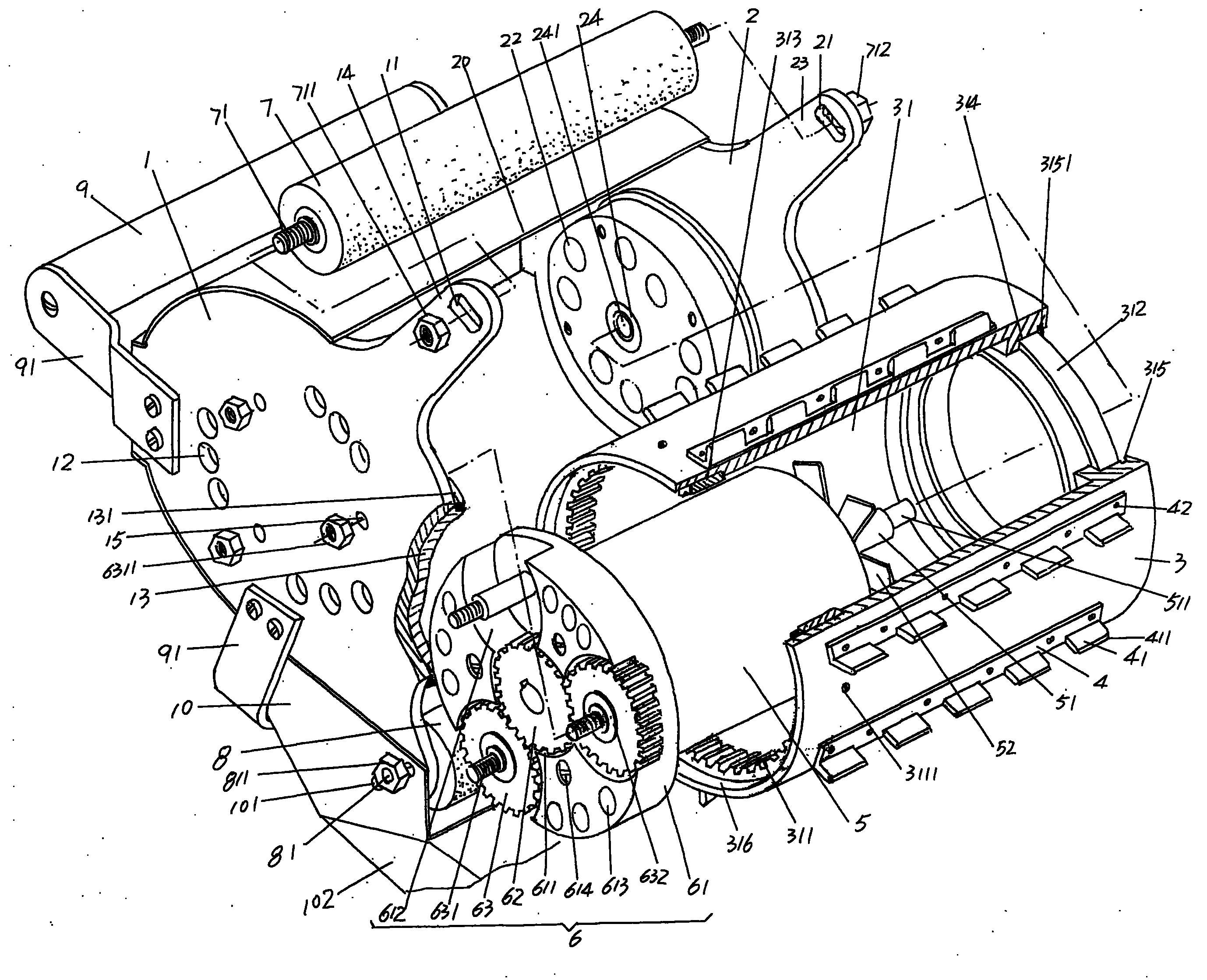
[0025] First of all, what the applicant needs to explain is: in the following description, all concepts related to orientation, such as left and right, are for the position status shown in the illustration, so this should not be interpreted as a limitation to the solution of the present invention; Secondly, the embodiment is only one of the best implementation modes recommended by the applicant, so it should not be regarded as unique and limit the solution of the present invention.

[0026] please see figure 1, the first and second support plates 1 and 2 which are set facing each other and have the same shape and size are provided, and the upper and lower parts of the first support plate 1 each extend a first support plate guide roller seat 14 in a narrow form, And the upper and lower parts of the second bracket plate 2 also extend a second bracket plate guide roller seat 23 in a narrow form. The concept of narrowing here is like the relationship between the auricle and the ea...


PUM


Abstract

The invention relates to a device for eliminating a wall surface coating, which belongs to apparatus for decoration constructions of wall surface of buildings. The device comprises a first supporting plate, a second supporting plate, a roller, a group of planer tool posts, a motor, a transmission mechanism meshed with a gear ring, an upper guide roll, a lower guide roll and a pair of handles, wherein one end of the roller is fixedly provided with the gear ring while the other end is fixedly provided with a roller bearing, and the second supporting plate is fixed with the roller bearing; the planer tool posts are arranged on the outer wall of the roller at intervals, and planer tools are arranged at intervals on each planer tool post; the motor is arranged in a roller cavity, and the right end of a motor shaft is arranged on the second supporting plate; the transmission mechanism is arranged at one end of the motor, facing the first supporting plate and is connected with the left end of the motor shaft; the upper guide roll and the lower guide roll are fixed on the first supporting plate and the second supporting plate; and the two handles are fixed with the first supporting plate and the second supporting plate respectively. The device has the advantages that the device has a compact structure, a small volume and ideal equitability, is favorable for reducing the operating strength of constructors, is convenient to replace, is favorable for comprehensively and uniformly eliminating an obsolete mortar bed, a coating or an oil paint on a wall body without generating missed planing and white flying phenomena, and is helpful for combining a new decorative layer with the wall body reliably.

Description

technical field [0001] The invention belongs to the technical field of construction equipment for building wall decoration, and in particular relates to a wall coating removal device, which is used to remove lime-like coatings and paint-like old coatings on the surface of cement mortar building walls . Background technique [0002] As we all know, coating paint or paint on the interior and exterior walls of buildings can play an ideal decorative role. However, as time goes by, surface coatings such as paint or paint will gradually lose their beauty due to aging, and even produce Cracking and peeling will affect the view, so it is often necessary to redecorate the wall surface. [0003] At present, when building metope (inner wall and outer wall, hereinafter the same) is redecorated, due to the lack of suitable tools, the original operation method is usually used for construction. The so-called original operation method refers to the use of chisels, chisels, A shovel or sim...

Claims


Application Information

Patent Timeline
Patent Type & Authority Applications(China)
IPC IPC(8): E04F21/00
Inventor 李国文张凯闫晶尹立新
Owner CHANGSHU INSTITUTE OF TECHNOLOGY
Why Eureka
Try Eureka