Optical communication system and arrangement converter

A technology of optical communication systems and converters, applied in transmission systems, electromagnetic wave transmission systems, instruments, etc.

Active Publication Date: 2010-07-21
SUMITOMO ELECTRIC IND LTD
View PDF4 Cites 18 Cited by
  • Summary
  • Abstract
  • Description
  • Claims
  • Application Information

AI Technical Summary

Problems solved by technology

[0006] However, in the PON system in which multiple subscribers share one optical fiber by inserting multi-stage optical splitters as described above, technologies such as congestion control (Congestion Control) and ensuring the dynamic range of reception exist for future increase in transmission capacity. topic

Method used


Image

  • Optical communication system and arrangement converter
  • Optical communication system and arrangement converter
  • Optical communication system and arrangement converter

Examples


Embodiment approach 1

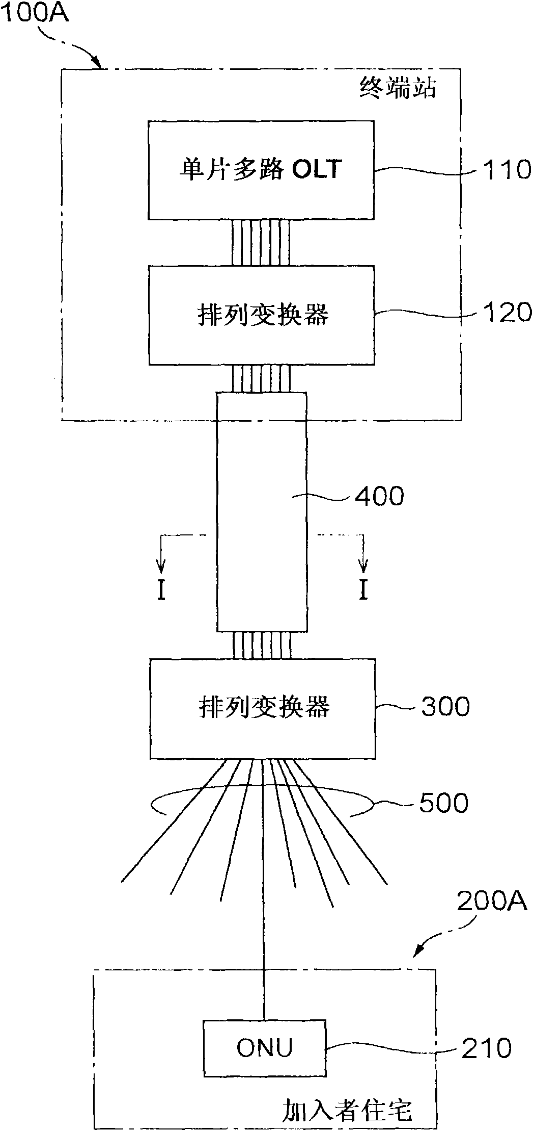
[0042] figure 1 It is a diagram showing the configuration of Embodiment 1 of the optical communication system according to the present invention.

[0043] The optical communication system according to Embodiment 1 and Figure 17 Similarly, FTTH (Fiber To The Home) service that enables optical communication between one sending station and multiple subscribers is provided. but, figure 1 The optical communication system shown is an SS (Single Star) system in which a plurality of signal channels are output from a transmission station via a multi-core optical fiber.

[0044] That is, the SS system according to Embodiment 1 includes: a terminal station 100A (sending station) serving as the final relay station of an existing communication system such as the Internet; a subscriber house 200A (subscriber); and a multi-core optical fiber 400, which constitutes A part of the optical fiber network laid between the terminal station 100A and the subscriber house 200A (subscriber), and h...

Embodiment approach 2

[0079] Figure 15A and 15B It is a diagram showing the configuration of Embodiment 2 of the optical communication system according to the present invention. The optical communication system according to Embodiment 2 is the same as Embodiment 1. It is an SS (Single Star) system in which a plurality of signal channels are output from a terminal station 100B as a transmission station via a multi-core optical fiber 400. FTTH (Fiber To The Home) service for performing optical communication between 100B and a plurality of subscribers 200B.

[0080] That is, the SS system related to Embodiment 2 is as follows Figure 15B As shown, there are: a terminal station 100B (sending station), which is the final relay station of an existing communication system such as the Internet; a subscriber house 200B (subscriber); and a multi-core optical fiber 400, which constitutes It is a part of an optical fiber network laid between houses 200B (subscribers), and has a plurality of cores (optical ...

Embodiment approach 3

[0085] Figure 16A and 16B It is a diagram showing the configuration of Embodiment 3 of the optical communication system according to the present invention. The optical communication system involved in Embodiment 3 is a many-to-many high-capacity optical communication system constructed by realizing the transmission and reception of multiple signal channels via a multi-core optical fiber 400, such as Figure 16BShown has: sending station 100C;; receiving station 200C; Multiple cores (optical waveguide regions) arranged in two dimensions. However, the difference between the optical communication system according to Embodiment 3 and Embodiment 2 is that the receiving station 200C has a single-chip multi-channel photosensitive element 250 having a plurality of photosensitive regions 250a arranged two-dimensionally. (corresponding to the respective cores of the multi-core optical fiber 400).

[0086] In the optical communication system according to the third embodiment, as in ...


PUM


Abstract

The present invention relates to an optical communication system or the like, which comprises a multicore fiber with a plurality of cores that are two-dimensionally arrayed in a cross-section thereof. In the optical communication system, an arrangement converter, provided between a multicore fiber and an Optical Line Terminal (OLT) having light emitting areas arrayed one-dimensionally, comprises first and second end faces, and a plurality of optical waveguides. The optical waveguides are disposed such that one of the end faces coincides with the first end face and the other end face coincides with the second end face. In particular, the optical waveguide end face array on the first end face and the optical waveguide end face array on the second face are different, contributing to an optical link between network resources of different types.

Description

technical field [0001] The present invention relates to an optical communication system and an array transducer. As a part of an optical fiber network, the optical communication system has a multi-core optical fiber in which a plurality of cores are two-dimensionally arranged in its section. The array transducer can be used as an array transducer. Connectors used in optical communication systems are used to achieve good optical coupling between various network resources. Background technique [0002] Currently, in order to provide FTTH (Fiber To The Home) services that enable optical communication between one sending station and multiple subscribers, for example Figure 17 As shown, a so-called PON (Passive Optical Network) system is realized, which enables each joiner to share one optical fiber by inserting a multi-stage optical splitter. [0003] which is, Figure 17 The PON system shown has: a terminal station 1 (sending station), which serves as the final relay station o...

Claims


Application Information

Patent Timeline
Patent Type & Authority Applications(China)
IPC IPC(8): G02B6/42G02B6/04H04B10/12H01L31/10H01L33/02H01L33/08
CPCG02B6/4472G02B6/4249G02B6/3879G02B6/264G02B6/02042
Inventor 屉冈英资
Owner SUMITOMO ELECTRIC IND LTD
Why Eureka
Try Eureka