
Nanomanipulation method for compounding laser near-field optical tweezers and AFM probe

A nano-manipulation and near-field light technology, applied in scanning probe technology, scanning probe microscopy, measurement devices, etc. Field fiber probe low-pass optical efficiency and other issues, to achieve the effect of convenient optical trap position and intensity, balance external interference force, and simple structure

Inactive Publication Date: 2010-07-28
HARBIN INST OF TECH
View PDF0 Cites 27 Cited by
  • Summary
  • Abstract
  • Description
  • Claims
  • Application Information

AI Technical Summary

Problems solved by technology

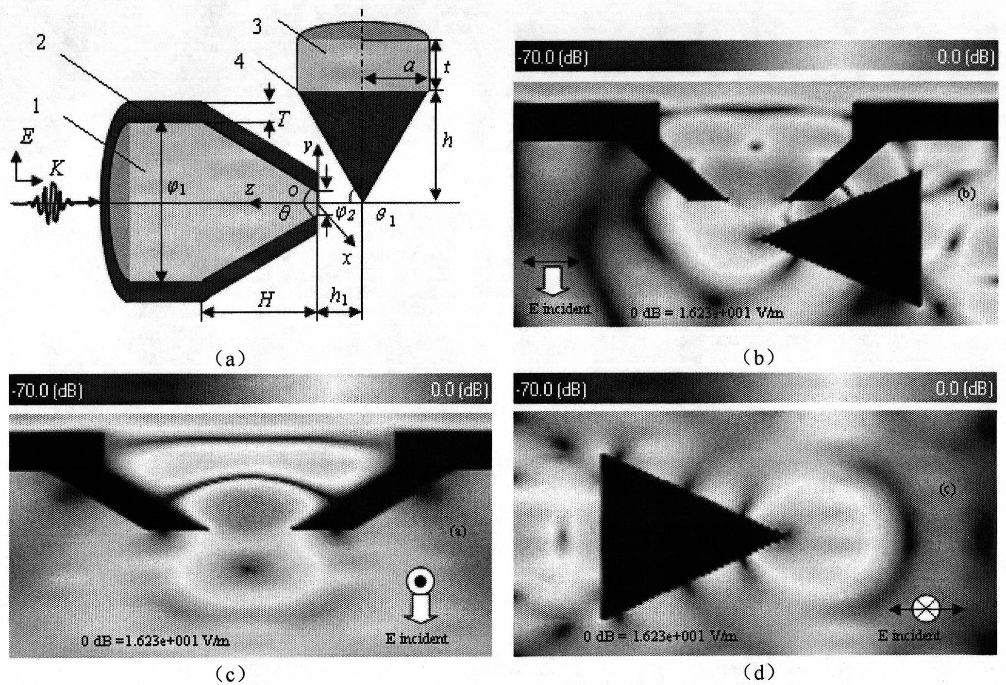
This method is more flexible than traditional optical tweezers. The optical fiber probe is inserted into the sample cell to increase the operating range of particles, and the operating accuracy has also developed from micron to nanoscale. However, this method is currently limited to theoretical numerical simulation research. The extremely low light transmission efficiency of near-field fiber optic probes hinders its development. The weak evanescent field makes it difficult for near-field optical tweezers to operate in liquids, and it is even more difficult to selectively capture nanoparticles in vacuum or air.
In addition, the observation and positioning of single nanoparticles by near-field optical tweezers is mainly to judge whether the particles are captured by measuring the intensity of scattered light. This method can only judge the status of a group of nanoparticles and is not suitable for Observation and localization of individual nanoparticles
Because it cannot be directly observed, it is difficult to find and directly locate nanoparticles. Therefore, in order to realize the operation of single nanoparticles by near-field optical tweezers, it is necessary to solve the problem of precise observation and positioning of single nanoparticles.

Method used


Image

  • Nanomanipulation method for compounding laser near-field optical tweezers and AFM probe
  • Nanomanipulation method for compounding laser near-field optical tweezers and AFM probe
  • Nanomanipulation method for compounding laser near-field optical tweezers and AFM probe

Examples


Embodiment 1

[0039] Embodiment 1: The operation of nanoparticles is realized by using a nano-manipulation method in which a single-fiber probe-type near-field optical tweezers is combined with an AFM probe.

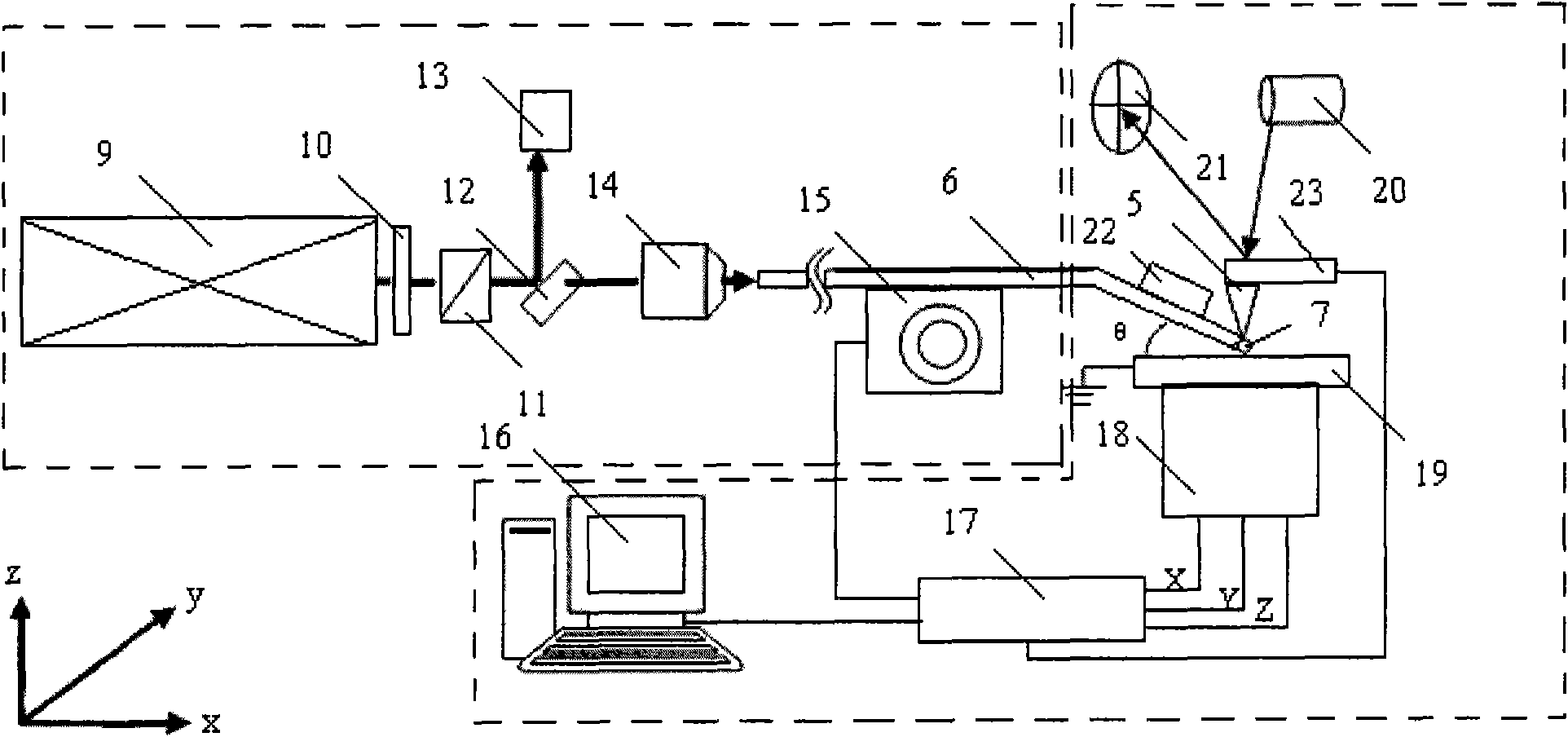
[0040] The structure diagram of the method is as follows image 3 shown, combined with image 3 The specific steps of the composite nano-operation method are described in detail as follows:

[0041] The output laser light of the He-Ne laser 9 passes through the half-wave plate 10 and splits out a beam of light which is monitored by the power detection joule meter 13 , and then enters the fiber probe 6 from the fiber coupler 14 . First, the AFM probe 5 is approached to the sample by using the scanning micro-feeding system of the AFM, and the single nanoparticle 7 is precisely positioned, and then the three-dimensional adjustment table 15 is controlled by the feedback information generated by the distance measurement controller 22 to drive the optical fiber probe 6 to make it The AFM ...

Embodiment 2

[0042] Example 2: Complicated three-dimensional operations are performed by using a double-fiber probe-type near-field optical tweezers combined with an AFM probe.

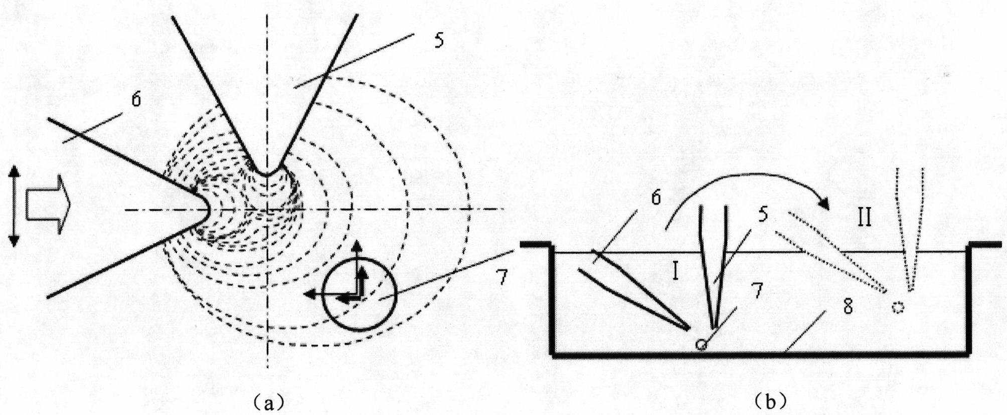
[0043] The principle structure of the method is as follows Figure 4 shown, combined with Figure 4 The specific steps of the complex three-dimensional operation method are described in detail as follows:

[0044] Firstly, the coarse adjustment system of AFM is used to roughly select the sample area with suitable density and dispersion, and then the scanning micro-feeding system of AFM is used to bring the AFM probe 5 close to the nanoparticle 7 to precisely position the single nanoparticle 7. After the selected location of the nanoparticles 7 is determined, the distance between the fiber probe 6 and the AFM probe 5 is reduced to the near-field range by using the three-dimensional adjustment stage 15, and the distance measuring controller 22 is used to keep the two at a certain distance during the micro-approxima...


PUM


Abstract

The invention relates to a nanomanipulation method for compounding laser near-field optical tweezers and an AFM probe. In the method of the invention, optical fiber probe type near-field optical tweezers are introduced into a sample chamber from an interface of an AFM system sample chamber with the outside, and a coupling force effect generated after compounding is used for carrying out sample particle nanomanipulation. After the AFM probe is positioned in the near-field region of the optical fiber probe, a three-dimensional stable light trap formed by coupling locally enhanced light field of the AFM probe and the optical fiber probe emergent light field can balance external interference, and realize stable and efficient trapping of nanoparticles.

Description

technical field [0001] The invention belongs to the field of near-field optics and nanometer operation, in particular to a nanometer operation method in which laser near-field optical tweezers and AFM probes are combined. Background technique [0002] Since 1990, when D. Eigler and others at IBM's Almaden Research Center in San Jose, USA realized atomic relocation for the first time, nanomanipulation began to attract the attention of scholars. Nanomanipulation refers to operations such as pushing, pulling, positioning, and shearing of nanoscale objects through external force application and sensor feedback. In recent years, the conductive connection of nanostructure nodes and the link packaging of nanoelectronic devices and external circuits have made precise nanomanipulation techniques more and more important. At present, nano-manipulation technology has been highly valued by various developed countries and has made some progress. With the help of nano-manipulation technol...

Claims


Application Information

Patent Timeline
Patent Type & Authority Applications(China)
IPC IPC(8): G01Q30/20G01Q60/24G01Q60/38
Inventor 杨立军王扬刘炳辉王懋露
Owner HARBIN INST OF TECH
Learn More