
Thin film transistor array substrate

A technology of thin film transistors and array substrates, which is applied in the field of liquid crystal display, can solve the problems of increasing laser cutting process, complicated testing process, and reliability problems, so as to improve production efficiency and product yield, improve reliability, and avoid electrical problems. problem effect

Active Publication Date: 2010-07-28
BEIHAI HKC OPTOELECTRONICS TECH CO LTD
View PDF0 Cites 15 Cited by
  • Summary
  • Abstract
  • Description
  • Claims
  • Application Information

AI Technical Summary

Problems solved by technology

The disadvantage of this method is that the laser cutting process is added, which affects the improvement of production efficiency
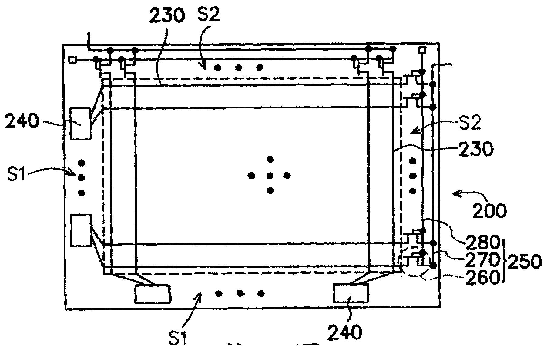
[0009] However, in the second method, an additional high-level control signal needs to be input to the control line 280 during the test, and an additional low-level signal needs to be added to the thin film transistor 260 when the liquid crystal display is working normally, so as to ensure The thin film transistor 260 will not cause related electrical defects, which not only makes the testing process more complicated, but also adds an additional low-level signal during normal operation, which may easily lead to reliability problems

Method used


Image

  • Thin film transistor array substrate
  • Thin film transistor array substrate
  • Thin film transistor array substrate

Examples


Embodiment 1

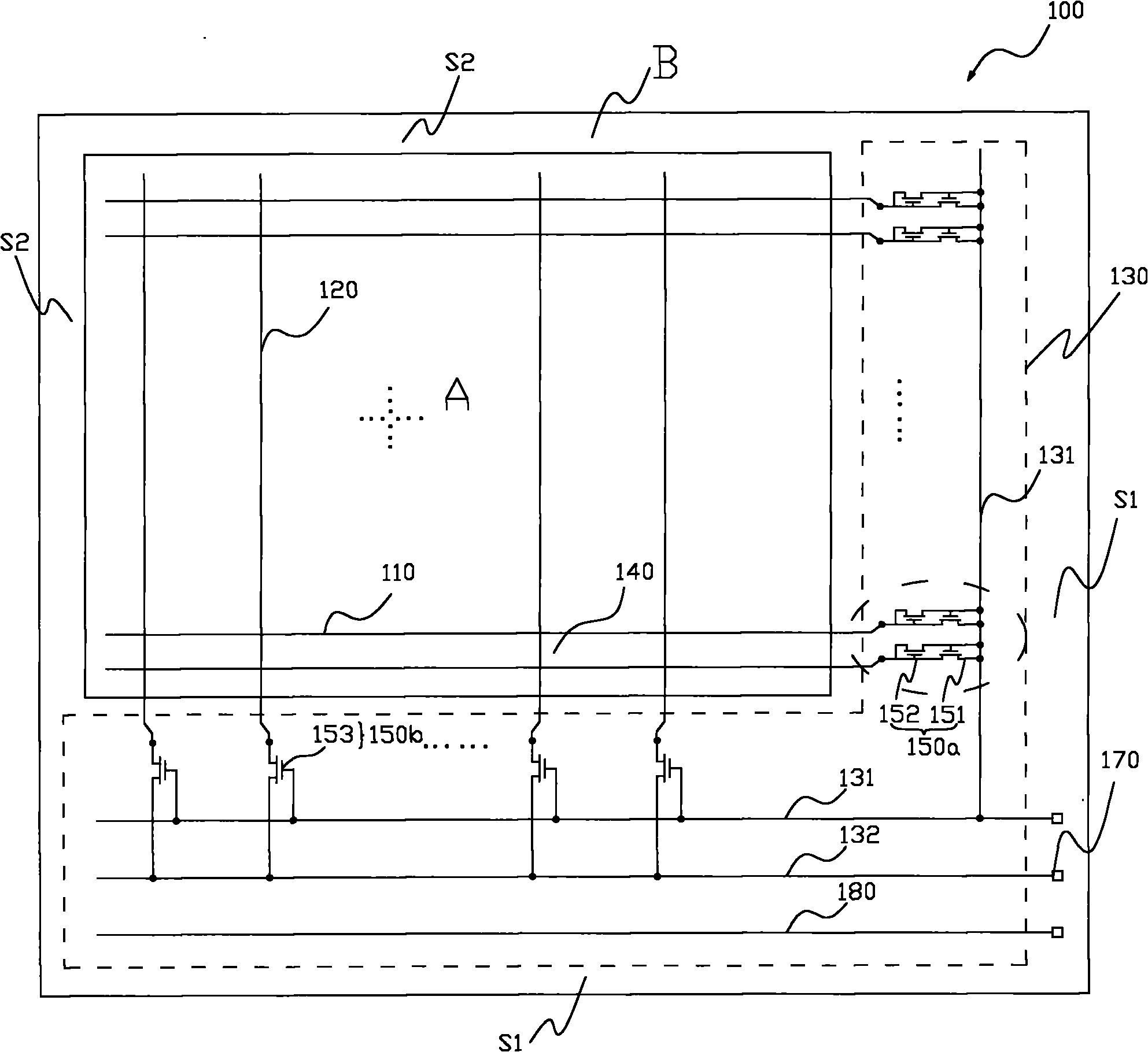
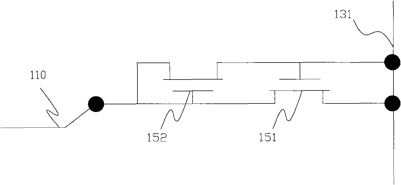
[0066] figure 2 It is a schematic diagram of the thin film transistor array substrate in this embodiment, image 3 It is a partially enlarged view of the test device in the array substrate.

[0067] like figure 2 and image 3 As shown, the thin film transistor array substrate 100 at least includes: at least two gate lines 110 and at least two data lines 120 arranged across each other on the substrate 100 , and the gate lines 110 and data lines 120 are coupled The testing device 130.

[0068] Wherein, the at least two gate lines 110 are arranged in parallel with the same spacing, and at least two data lines 120 are also arranged in parallel with the same spacing along the direction perpendicular to the gate lines 110; the gate lines 110 and data lines 120 crosses and separates an array of pixel units 140, and each pixel unit includes at least one pixel thin film transistor (not shown in the figure), the gate of the pixel thin film transistor is connected to the gate line ...

Embodiment 2

[0092] Figure 7 It is a schematic diagram of the thin film transistor array substrate in this embodiment, Figure 8 It is a partial enlarged view of the test device in the substrate.

[0093] like Figure 7 As shown, in this embodiment, the test device 330 for the thin film transistor array substrate 300 includes: a data test unit 350b, and at least two short-circuit bars 331 for gate lines and at least two short-circuit bars 332 for data lines; wherein, the data The test unit 350b includes a third thin film transistor 353 and a fourth thin film transistor 354 coupled to each other, and the data line short bar 332 and the gate line short bar 331 pass through the third thin film transistor 353 and the fourth thin film transistor 354 coupled to each other. Connect with each data line set.

[0094] Specifically, at least two gate lines 310 are divided into two gate line groups 310a, 310b. For example, counting from top to bottom, the even-numbered gate line belongs to the gat...


PUM


Abstract

The invention provides a thin film transistor array substrate which comprises at least two gate lines, at least two data lines and a testing device, wherein the gate lines and the data lines are mutually crosswise arrayed; and the testing device is positioned in a non-display area and coupled with the gate lines and the data lines. The testing device comprises a scan testing unit, a data testing unit, a gate line short circuit rod and a data line short circuit rod, wherein the scan testing unit is connected with the gate lines; the data testing unit is connected with the data lines; and the gate line short circuit rod is respectively connected with the switch end of the scan testing unit and the switch end of the data testing unit and used for controlling the on-off of the scan testing unit and the data testing unit. In an electrical testing process, the thin film transistor array substrate does not need extra control signals, and when the thin film transistor array substrate normally works, extra low level signals do not need to be input.

Description

technical field [0001] The invention relates to the technical field of liquid crystal display, in particular to a thin film transistor array substrate. Background technique [0002] In recent years, with the rapid development of the information and communication field, various types of display devices are in increasing demand. The current mainstream display devices mainly include: cathode ray tube display, liquid crystal display (LiquidCrystal Display, LCD), plasma display, electroluminescent display and vacuum fluorescent display. Among them, LCD has become the mainstream trend in the development of display devices due to its high-definition, true-color video display, light and thin appearance, low power consumption, and no radiation pollution. [0003] Generally, an LCD includes a liquid crystal display panel for displaying pictures and a driving circuit module for providing driving signals to the liquid crystal display panel, and the liquid crystal display panel usually ...

Claims


Application Information

Patent Timeline
IPC IPC(8): G02F1/1362G02F1/13H01L27/12
Inventor 荆常营蒋顺
Owner BEIHAI HKC OPTOELECTRONICS TECH CO LTD
Learn More