This helps you quickly interpret patents by identifying the three key elements:
Problems solved by technology
Method used
Benefits of technology
Problems solved by technology
[0026] In the bearing described in Patent Document 4, it is necessary to form an inclined surface on the inner peripheral surface side of the divided surface of the outer ring, and there is a problem that the processing is complicated and thus the manufacturing cost increases.
[0027] In addition, in the bearing described in Patent Document 5, the outer ring needs to be thickened, and hardening such as quenching and grinding is required, and the processing is complicated, resulting in an increase in manufacturing cost.
Method used
Image
Click on the blue label to locate the original text in one second.
Reading with bidirectional positioning of images and text.
Examples
no. 1 approach
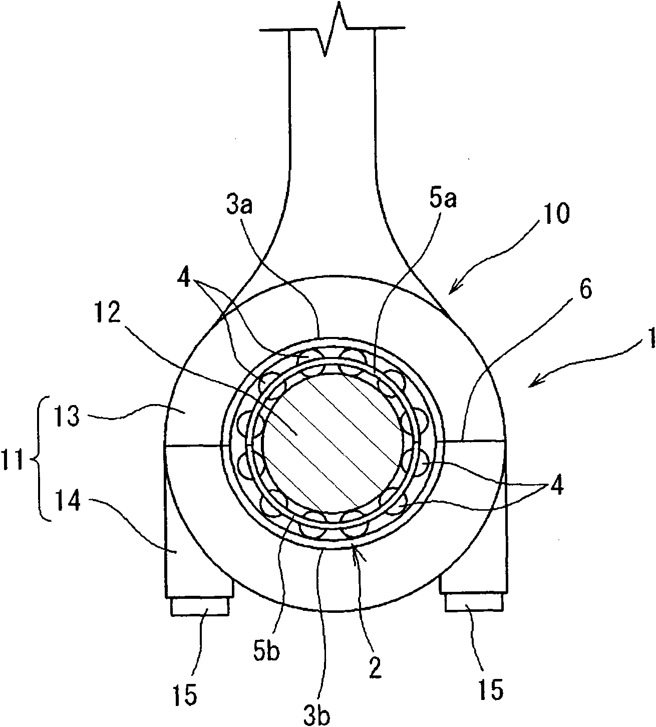
[0081] figure 1 It is a cross-sectional explanatory view of the large end of the connecting rod to which the bearing structure 1 of the first embodiment of the present invention is applied. The large end 11 of the connecting rod 10 is supported by the crankshaft 12, and a piston (not shown) is attached to a small end (not shown) via a pin.
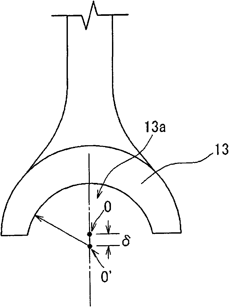
[0082] The above-mentioned large end portion 11 is formed by connecting and fixing the second housing portion, which is the cover portion 14, which has a substantially semicircular cross-section, to the main body portion 13, which has a substantially semicircular cross-section, with bolts 15 The support hole 16 has a substantially circular cross-section. The split type rolling bearing 2 is inserted into the support hole 16 formed by the main body portion 13 and the cover portion 14 with a substantially circular cross section.
[0083] The rolling bearing 2 includes two sets of split outer rings 3a, 3b arranged in close contact in the support ...
no. 2 approach
[0092] Figure 5 It is a cross-sectional explanatory view of the large end 111 of the connecting rod 110 using the bearing structure 101 of the second embodiment of the present invention. The connecting rod 110 has a structure in which a split-type rolling bearing 102 is inserted into a support hole 116 of a large end 111 which is a shell formed by a first shell piece 113 and a second shell piece 114, and a crankshaft 112 is further embedded. In this specification, the bearing structure 101 is called by the shell ( Figure 5 Among them, the first housing part 113, the second housing part 114), and the split type rolling bearing 102 constitute a structure.
[0093] The split rolling bearing 102 consists of split outer rings 103a, 103b, a plurality of rolling elements 104, 104 arranged to be rollable on the inner surfaces of the split outer rings 103a, 103b, and a plurality of the rolling elements 104, 104 is constituted by split type holders 105a and 105b that are held at predeter...
no. 3 approach
[0107] Picture 9 It is a cross-sectional explanatory view of the large end of the connecting rod to which the bearing structure 201 of the third embodiment of the present invention is applied. The large end portion 211 of the connecting rod 210 is supported by the crankshaft 212, and a piston (not shown) is attached to the small end portion (not shown) via a pin.
[0108] The above-mentioned large end portion 211 is formed by connecting and fixing the cover portion 214, which is a second housing having a concave portion with a substantially semicircular cross-section, to the main body portion 213 having a concave portion having a substantially semicircular cross-section with a bolt 215 to form a substantially circular cross section The structure of the support hole 216. The split type rolling bearing 202 is inserted into the support hole 216 formed by the main body portion 213 and the cover portion 214 with a substantially circular cross section.
[0109] The rolling bearing 202 ...
PUM
Abstract
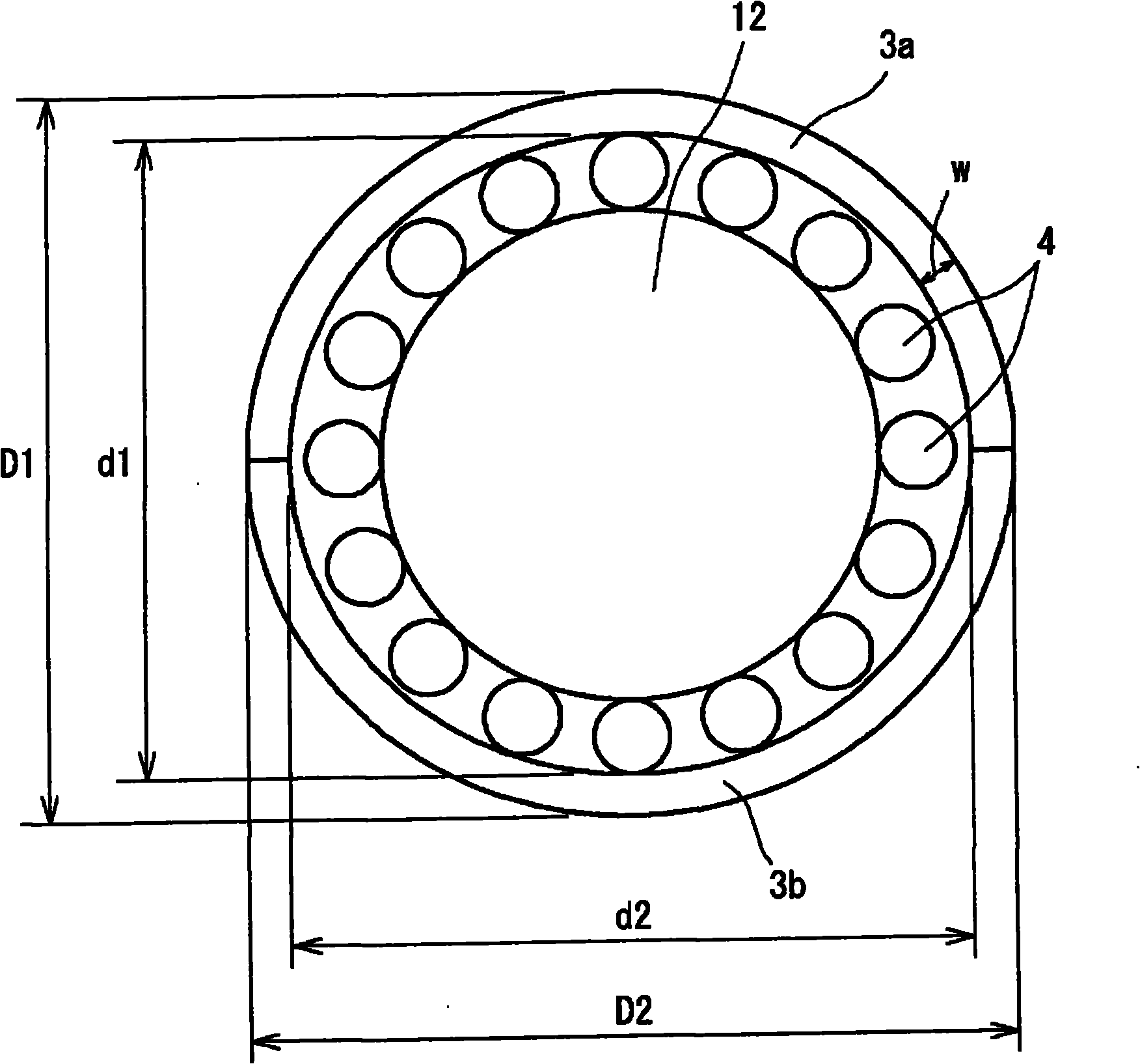
Provided is a bearing structure, which can be simply worked and lowered in its manufacturing cost. The bearing structure (1) comprises a housing including a first housing portion (13) having a recess of a substantially semicircular section and a second housing portion (14) having a recess of a substantially semicircular section and forming a supporting hole (16) of a substantially circular section together with the recess (13a) of the first housing portion (13). Further comprised are two halved roller bearings (2) having a shaft (12) fitted therein. The two halved roller bearings (2) include one set of two halved outer rings (3a and 3b) arranged closely in the supporting hole (16) of that housing, a plurality of rolling elements (4) arranged to roll on the individual inner sides faces of the two halved outer rings (3a and 3b), and one set of two halved retainers (5a and 5b) for retaining the individual rolling elements (4) arranged substantially equidistantly in the circumferential direction. The internal diameter of the supporting hole (16) in the direction of the mating faces of the housing portions is made larger than the internal diameter in the direction displaced by 90 degrees from that of the mating faces.
Description
Technical field [0001] The invention relates to a bearing structure and a manufacturing method thereof. In more detail, it relates to a bearing structure composed of a split type rolling bearing suitable for supporting shafts such as a crankshaft and a camshaft of an engine, and a housing supporting the rolling bearing, and a manufacturing method thereof. Background technique [0002] In engines such as automobiles and ships, the bearings that support the crankshaft that converts the reciprocating motion of the piston into rotational motion are arranged between the counterweight or between the counterweight and the large end of the connecting rod, so it is divided into two parts in the circumferential direction. Part of the split bearing (half bearing). [0003] The above-mentioned support bearings have used sliding bearings in the past. However, in recent years, due to the increasing demand for engines with less fuel consumption, in order to reduce the rotation loss, the use of s...
Claims
Application Information
Patent Timeline
Application Date:The date an application was filed.
Publication Date:The date a patent or application was officially published.
First Publication Date:The earliest publication date of a patent with the same application number.
Issue Date:Publication date of the patent grant document.
PCT Entry Date:The Entry date of PCT National Phase.
Estimated Expiry Date:The statutory expiry date of a patent right according to the Patent Law, and it is the longest term of protection that the patent right can achieve without the termination of the patent right due to other reasons(Term extension factor has been taken into account ).
Invalid Date:Actual expiry date is based on effective date or publication date of legal transaction data of invalid patent.

