Rotary fluidized drying device and method

A technology of boiling drying and crushing device, applied in the direction of dewatering/drying/concentrating sludge treatment, etc., can solve the problems of increasing equipment investment, kinetic energy consumption, operating cost, large power consumption, affecting drying efficiency, etc. The problem of hardening, the elimination of the possibility of deflagration, the effect of increasing the specific surface area

Inactive Publication Date: 2010-08-11
SOUTHEAST UNIV
View PDF4 Cites 10 Cited by
  • Summary
  • Abstract
  • Description
  • Claims
  • Application Information

AI Technical Summary

Problems solved by technology

[0004] At present, there are many forms of sludge drying devices, such as drum type, belt type, hollow paddle type, disc rotary type, swirl jet type, etc., but there are some technical problems as follows: ①It is easy to leak into the air
② Severe sticking to the wall
During the drying process, due to the strong adhesion of the sludge, the moisture content is slightly high and it is easy to adhere to the wall of the equipment, thereby affecting the drying efficiency, and even the drying system cannot operate normally due to the sludge clogging
③Large power consumption
In order to solve the problems of difficulty in controlling the oxygen content of the drying system and the clogging of the sludge wall, various technical measures have been adopted. Although the effects are different, they all greatly increase the equipment investment, kinetic energy consumption and Operating costs

Method used


Image

  • Rotary fluidized drying device and method
  • Rotary fluidized drying device and method

Examples


Embodiment Construction

[0019] Below, the present invention will be further described in conjunction with the accompanying drawings and embodiments.

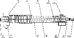
[0020] In the rotary boiling drying device of the present invention, a front bearing seat 11 and a rear bearing seat 6 are respectively provided at both ends of the body 8, the rotating shaft 9 is located in the body 8, and the two ends of the rotating shaft 9 are located in the front bearing seat 11 and the rear bearing seat 6 , one end of which is connected to the motor 12 through a transmission. On the rotating shaft 9 in the body 8, a crushing device 2, a propulsion device 3, and a scraper 4 are arranged in sequence from the front bearing seat 11 to the rear bearing seat 6. On the top of the crushing device 2 There is a wet sludge feeding port 1 on the side, and a high-temperature flue gas inlet 10 on the lower side; a low-temperature flue gas outlet 5 is arranged on the upper side of the scraper 4 at one end of the rear bearing seat 6, and a dry sl...


PUM


Abstract

The invention discloses a rotary fluidized drying device and a rotary fluidized drying method and relates to a drying device and a drying method applied to sludge treatment. In the device, the two ends of a machine body (8) is provided with a front bearing pedestal (11) and a rear bearing pedestal (6) respectively; a rotating shaft (9) is positioned in the machine body (8); the two ends of the rotating shaft (9) are positioned in the front bearing pedestal (11) and the rear bearing pedestal (6); one end of the rotating shaft (9) is connected with a motor (12) through a speed changer; a crushing device (2), a propulsion device (3) and a scraper plate (4) are arranged on the rotating shaft (9) of the machine body (8) from the front bearing pedestal (11) to the rear bearing pedestal (6) sequentially; a wet sludge charge opening (1) is arranged on the upper side of the crushing device (2); a high-temperature smoke inlet (10) is arranged on the lower side of the crushing device (2); a low-temperature smoke outlet (5) is arranged on the upper side of the scraper plate (4) at one end of the rear bearing pedestal (6); and a dry sludge discharge opening (7) is arranged on the lower side of the scraper plate (4) at one end of the rear bearing pedestal (6). The device can realize the continuous operation of sludge drying and has the advantages of high production efficiency, low heat consumption and particularly low power consumption.

Description

technical field [0001] The invention relates to a drying device and a drying method for sludge disposal, in particular to a rotary boiling drying device and a method. Background technique [0002] Sludge is the product of sewage treatment. Due to its high water content, complex composition, and more organic matter, it has a certain viscosity. At present, the disposal methods of sludge are mainly landfill and composting. Landfill disposal method will occupy a large amount of land resources and easily cause secondary pollution. According to the methods of sterilization and aging, compost has different fertilizer efficiency and safety. This disposal method can achieve the purpose of recycling, but the processing process is longer, and it will also occupy a large amount of land resources, and the disposal cost is also high; in addition, Sludge containing harmful components such as heavy metals should not be disposed of in this way. [0003] After drying, the sludge can be grea...

Claims


Application Information

Patent Timeline
Patent Type & Authority Applications(China)
IPC IPC(8): C02F11/12
Inventor 鲁维加徐久华郭宏伟
Owner SOUTHEAST UNIV
Why Eureka
Try Eureka