In-containing lead-free solder for on-vehicle electronic circuit

A technology of lead-free solder and on-board electronics, which is applied to the assembly of printed circuits, printed circuits, and printed circuit manufacturing of electrical components. It can solve the problems of not showing heat cycle resistance, etc., and achieve excellent heat cycle resistance, stability and reliability. , the effect of suppressing the deterioration of strength

Active Publication Date: 2010-08-11
SENJU METAL IND CO LTD
View PDF3 Cites 23 Cited by
  • Summary
  • Abstract
  • Description
  • Claims
  • Application Information

AI Technical Summary

Problems solved by technology

[0006] However, when the thermal cycle test currently required is performed on the soldered joint of the electronic circuit in the vehicle, it does not show sufficient thermal cycle resistance

Method used


Image

  • In-containing lead-free solder for on-vehicle electronic circuit

Examples


Embodiment

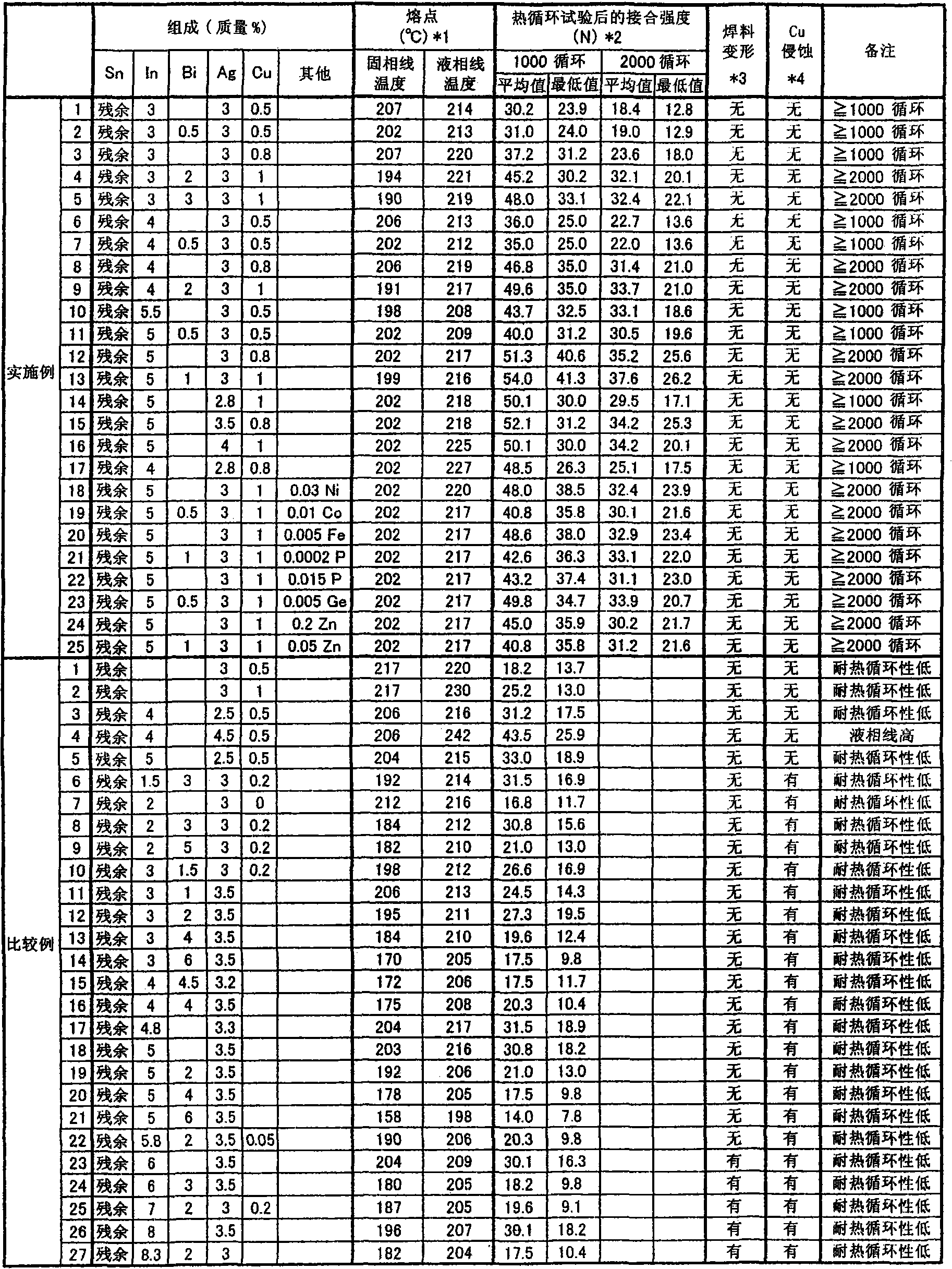
[0081] In this example, solder alloys having the respective compositions shown in Table 1 were prepared, and their properties were evaluated in the following manner.

[0082] Table 1 shows the compositions of the lead-free solders of Examples and Comparative Examples in the present invention.

[0083] [Table 1]

[0084] [Table 1]

[0085]

[0086] In this example, melting point measurement, heat cycle test, deformation test, and Cu corrosion test were performed for each solder alloy. The points of each test are as follows.

[0087] Melting point determination ( * 1):

[0088] The solidus temperature and liquidus temperature were measured by differential scanning calorimetry (DSC). The heating rate of the differential scanning calorimetry device was 5° C. / min, and the sample weight was 15 g.

[0089] In consideration of thermal influence on electronic components or printed circuit boards during soldering, the liquidus temperature is preferably 230° C. or lower. In add...


PUM


Abstract

Disclosed is a lead-free solder alloy having high reliability, which can be used for soldering an on-vehicle electronic circuit. Specifically disclosed is a lead-free solder alloy containing 2.8-4% by mass of Ag, 3-5.5% by mass of In, 0.5-1.1% by mass of Cu, additionally if necessary, 0.5-3% by mass of Bi, and the balance of Sn. In this lead-free solder alloy, In is solid-solved in at least a part of the Sn matrix.

Description

technical field [0001] The present invention relates to a lead-free solder used under severe conditions with large temperature changes, for example, a lead-free solder for automotive electronic circuits used in an environment where the temperature difference between the time of use and the time of stop becomes large, such as near the engine of an automobile, and its use. Its on-board electronic circuit. Background technique [0002] Since lead has a bad influence on the human body, the incorporation of lead into solder has been restricted, and lead-free solder whose main component is Sn has been used. At present, Sn-3Ag-0.5Cu solder is the lead-free solder used more in so-called "civilian electronic equipment" such as TV sets, video recorders, mobile phones, and notebook computers. Compared with the conventional Pb-Sn solder, this lead-free solder is slightly inferior in solderability, and it can be used without any problem with the improvement of flux or soldering equipmen...

Claims


Application Information

Patent Timeline
Patent Type & Authority Applications(China)
IPC IPC(8): B23K35/26C22C13/00H05K3/34
CPCB23K35/262B23K35/26H05K3/3463C22C13/00
Inventor 川又勇司上岛稔田村丰武松下和裕坂本真志
Owner SENJU METAL IND CO LTD
Why Eureka
Try Eureka