
Device for milling round pit on asphalt pavement

A technology of asphalt pavement and milling, which is applied in the direction of roads, roads, road repair, etc., to improve the quality and service life of pavement maintenance, overcome the overall poor quality, and facilitate the operation.

Inactive Publication Date: 2011-08-03
CHANGAN UNIV
View PDF0 Cites 0 Cited by
  • Summary
  • Abstract
  • Description
  • Claims
  • Application Information

AI Technical Summary

Problems solved by technology

However, just because of the cylindrical horizontal milling drum of this milling machine, the milling drum rotates around its horizontal axis during the straight running of the milling machine, so that the front and rear sides of the quadrilateral pit formed by the milling road surface are not vertical. , but arcs with different depths. In order to ensure that the four sides of the pit are vertical and smooth, a cutting machine or manual trimming is required.

Method used


Image

  • Device for milling round pit on asphalt pavement
  • Device for milling round pit on asphalt pavement
  • Device for milling round pit on asphalt pavement

Examples


Embodiment 1

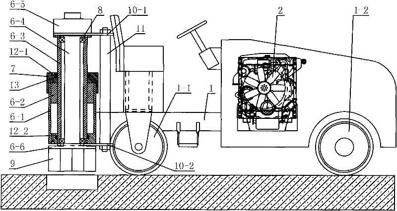
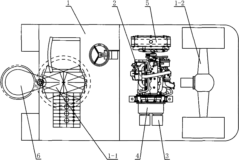
[0040] like figure 1 and figure 2The shown a kind of asphalt pavement circular pit milling equipment includes a self-propelled chassis 1 and an engine 2 installed on the self-propelled chassis 1, a hydraulic oil pump group 3, a transfer case 4 and a box assembly 5, the The engine 2 is installed in the middle of the self-propelled chassis 1, the transfer case 4 is installed at the output end of the flywheel of the engine 2, the hydraulic oil pump group 3 is installed at the output end of the transfer case 4, and the box assembly 5 is installed at the The left side of the engine 2 also includes a rotary lifting vertical milling device 6, and the rotary lifting vertical milling device 6 is installed on the self-propelled chassis 1 rear portion. Wherein, the rotary lifting vertical milling device 6 includes a cylinder 6-1, a lifting piston 6-2, a lifting piston rod 6-3, a milling mandrel 6-4, a milling hydraulic motor 6-5 and a milling cutter Disk 6-6, the lifting piston 6-2 an...

Embodiment 2

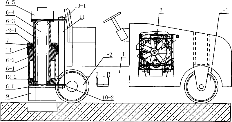
[0045] Such as image 3 with Figure 4 The shown a kind of asphalt pavement circular pit milling equipment includes a self-propelled chassis 1 and an engine 2 installed on the self-propelled chassis 1, a hydraulic oil pump group 3, a transfer case 4 and a box assembly 5, the The engine 2 is installed in the middle of the self-propelled chassis 1, the transfer case 4 is installed at the output end of the flywheel of the engine 2, the hydraulic oil pump group 3 is installed at the output end of the transfer case 4, and the box assembly 5 is installed at the The left side of the engine 2 also includes a rotary lifting vertical milling device 6, and the rotary lifting vertical milling device 6 is installed on the self-propelled chassis 1 rear portion. Wherein, the rotary lifting vertical milling device 6 includes a cylinder 6-1, a lifting piston 6-2, a lifting piston rod 6-3, a milling mandrel 6-4, a milling hydraulic motor 6-5 and a milling cutter Disk 6-6, the lifting piston 6...


PUM


Abstract

The invention discloses a device for milling a round pit on an asphalt pavement, which comprises a self-propelled frame, and an engine, a hydraulic oil pump group, a transfer case and a case assembly arranged on the self-propelled frame, wherein engine is arranged in the center of the self-propelled frame; the transfer case is arranged at a flywheel output end of the engine; the hydraulic oil pump group is arranged at an output end of the transfer case; and the case assembly is arranged on the left side of the engine. The device also comprises a rotary lifting vertical milling device which isarranged on the rear part of the self-propelled frame or on one side of the middle part of the self-propelled frame. The device has the advantages of simple structure, reasonable design, convenient operation and high practical value, can directly mill out the round pit with a regular shape and vertical edges, needs no manual or other auxiliary machines, not only greatly improves the operational efficiency of pavement maintenance and lightens the labor intensity but also improves the compaction uniformity of a new material and the bond strength between pavements, and further improves the pavement maintenance quality and prolongs the pavement service life.

Description

technical field [0001] The invention belongs to the technical field of asphalt pavement maintenance machinery, and in particular relates to a round pit milling equipment for asphalt pavement. Background technique [0002] For a long time, the repair of local damage to asphalt pavement at home and abroad has been square pits. The pit excavation equipment used in the early days includes cutting machines, pneumatic picks, hydraulic picks, and human picks. The excavation steps using these equipment are as follows: first use The cutting machine cuts quadrangular grooves of different sizes around the damaged pavement, and then uses pneumatic picks, hydraulic picks or human picks to loosen and remove the pavement materials in the quadrangular grooves to form square or rectangular pits with a certain depth. After the 1980s, a kind of asphalt pavement milling machine appeared. This milling machine has a cylindrical horizontal milling drum, which can mill square or rectangular pits on...

Claims


Application Information

Patent Timeline
Patent Type & Authority Patents(China)
IPC IPC(8): E01C23/09
Inventor 宋永刚
Owner CHANGAN UNIV
Learn More