Double-valve fuel injecting device with electric-control monoblock pump and electric-control fuel injector

An electronically controlled fuel injection and fuel injection technology, which is applied to fuel injection devices with oil reservoirs, fuel injection devices, fuel injection pumps, etc., can solve the problems of deterioration of the combustion process, low fuel injection pressure, and low reliability, etc. To achieve the effect of suppressing mutual interference, reducing power and improving economy

Inactive Publication Date: 2010-08-18
HARBIN ENG UNIV
View PDF4 Cites 35 Cited by
  • Summary
  • Abstract
  • Description
  • Claims
  • Application Information

AI Technical Summary

Problems solved by technology

[0003] At present, the electronically controlled fuel injection system applied to large and medium-sized diesel engines has been able to improve the control of fuel injection to a certain extent, but there are still many shortcomings that need to be further optimized and improved: 1. In addition to the common rail fuel injection system, The establishment of fuel injection pressure in diesel engine fuel injection system is closely related to the speed of diesel engine
When the diesel engine is at high speed, the fuel injection pressure is high, which can meet the requirements of fuel injection and combustion, but at low speed, the fuel injection pressure is low, and the atomization quality is poor, which will cause the combustion process to deteriorate, so that the economy of the diesel engine Poor, har

Method used


Image

  • Double-valve fuel injecting device with electric-control monoblock pump and electric-control fuel injector
  • Double-valve fuel injecting device with electric-control monoblock pump and electric-control fuel injector
  • Double-valve fuel injecting device with electric-control monoblock pump and electric-control fuel injector

Examples


Embodiment approach 1

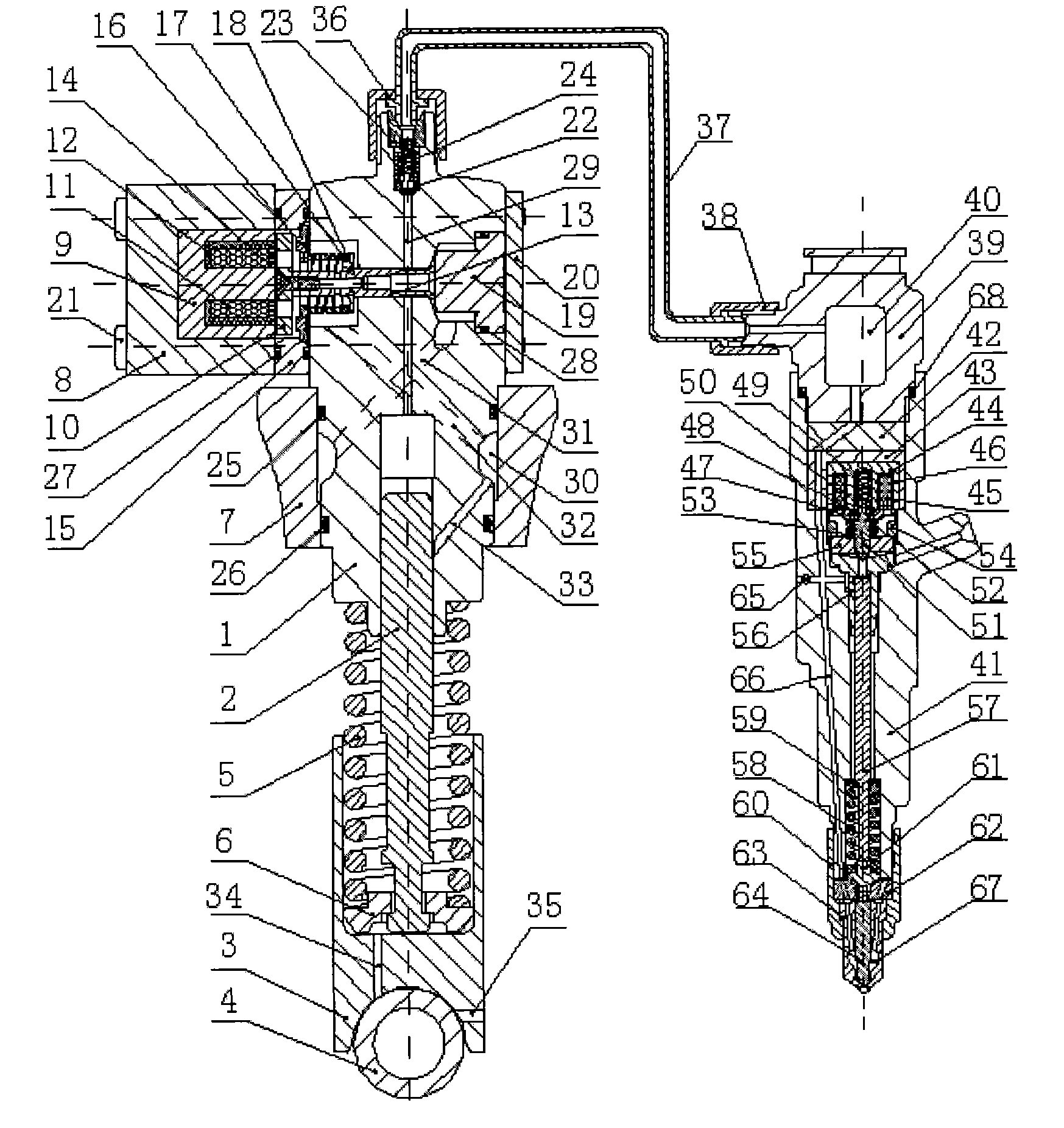
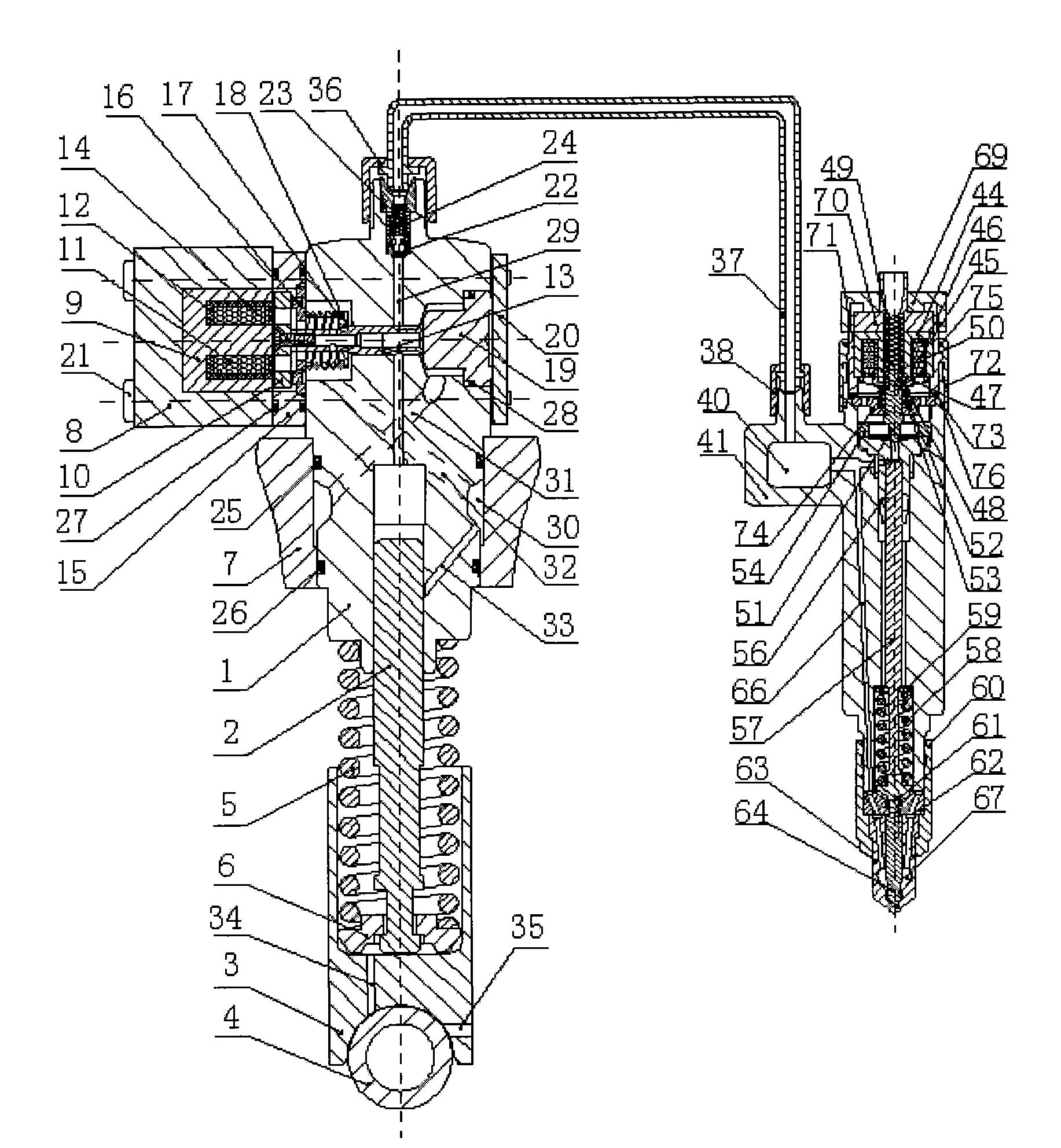
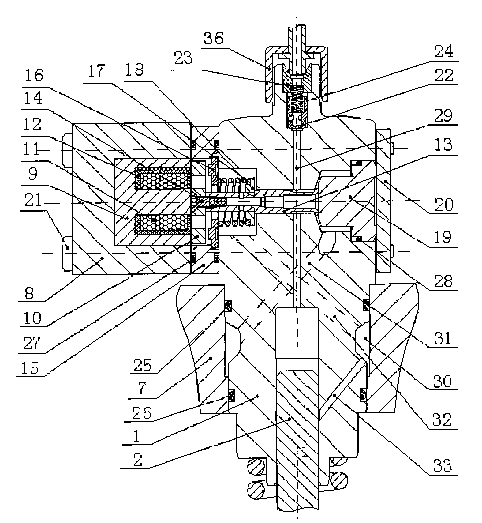
[0018] The pump body 1 of the electric control unit pump is installed in the pump box body 7, the control valve core 13 is installed in the valve core installation hole of the pump body 1, the solenoid valve body 8, the electromagnet 9, the armature 10, and the electromagnetic coil 11 , armature fastening screw 14, adjusting backing plate 15, block 16, control spool return spring 17, control spool spring seat 18, etc., together with control spool 13 constitute the oil supply solenoid valve control part of the monomer pump. The electromagnet 9, the adjusting backing plate 15 and the cover plate 20 are connected to the pump body 1 through the long bolts 21, and seal the fuel through the sealing rings 27 and 28. The pump body 1 is processed with a sealing tapered hole that fits with the sealing tapered surface of the control valve core 13, and this place is a fuel leakage channel. The armature 10 is integrated with the control spool 13 through the fastening screw 14, so that the ...

Embodiment approach 2

[0029] The pump body 1 of the electric control unit pump is installed in the pump box body 7, the control valve core 13 is installed in the valve core installation hole of the pump body 1, the solenoid valve body 8, the electromagnet 9, the armature 10, and the electromagnetic coil 11 , armature fastening screw 14, adjusting backing plate 15, block 16, control spool return spring 17, control spool spring seat 18, etc., together with control spool 13 constitute the oil supply solenoid valve control part of the monomer pump. The electromagnet 9, the adjusting backing plate 15 and the cover plate 20 are connected to the pump body 1 through the long bolts 21, and seal the fuel through the sealing rings 27 and 28. The pump body 1 is processed with a sealing tapered hole that fits with the sealing tapered surface of the control valve core 13, and this place is a fuel leakage channel. The armature 10 is integrated with the control spool 13 through the fastening screw 14, so that the ...


PUM


Abstract

The invention provides a double-valve fuel injecting device with an electric-control monoblock pump and an electric-control fuel injector, comprising the electric-control monoblock pump, a high-pressure fuel pipe and the electric-control fuel injector. The double-valve fuel injecting device is characterized in that a pressure accumulator and electromagnetic valves are arranged on the electric-control fuel injector, an inlet of the pressure accumulator is connected with the electric-control monoblock pump through the high-pressure fuel pipe, an outlet of the pressure accumulator is connected with a fuel inlet hole of the electric-control fuel injector, and the electromagnetic valves are installed on a throttle valve of the electric-control fuel injector and are connected with the throttle valve. Through the matching control on the electromagnetic valves of the monoblock pump and the electric-control fuel injector, the double-valve fuel injecting device can eliminate the influence of the rotary speed of a diesel engine on fuel injection pressure, inhibit the influence of pressure oscillation in the fuel injection process on the fuel injection, and flexibly control accumulating pressure before the fuel injection and the opening pressure of a fuel injection needle valve, thereby realizing the flexible control on the fuel injection pressure and the injection rule; and then the double-valve fuel injecting device satisfies the requirements of the diesel engine for the fuel injection when the diesel engine runs under different working conditions, improves the economical efficiency and the dynamic property of the diesel engine, and reduces the discharge of harmful matters.

Description

technical field [0001] The invention relates to a fuel injection device, in particular to a fuel injection device meeting the injection requirements of large and medium-sized diesel engines under all working conditions. Background technique [0002] In recent years, electronically controlled fuel injection technology for diesel engines has developed rapidly, and more and more diesel engines are equipped with electronically controlled fuel injection systems. Generally, the electronically controlled fuel injection system includes electronically controlled unit pumps, high-pressure oil pipes and fuel injectors. Using the rapid response of electronically controlled devices, it can realize fast and accurate control of the fuel injection quantity and injection law of the diesel engine, so as to improve the quality of the diesel engine. The purpose of economy, power and reduction of harmful emissions. [0003] At present, the electronically controlled fuel injection system applied...

Claims


Application Information

Patent Timeline
IPC IPC(8): F02M51/06F02M47/02
CPCF02M47/027F02M59/102F02M59/36F02M2200/40
Inventor 范立云田丙奇马修真
Owner HARBIN ENG UNIV
Why Eureka
Try Eureka