Multichannel array signal generating method and device

An array signal and generating device technology, which is applied in the fields of sonar, radar and wireless communication, can solve the problems of poor control of data update synchronization, large size, and complicated implementation process.

Inactive Publication Date: 2010-08-18
ZHEJIANG UNIV
View PDF7 Cites 13 Cited by
  • Summary
  • Abstract
  • Description
  • Claims
  • Application Information

AI Technical Summary

Problems solved by technology

Like this, this technology just has following shortcoming: the pin number resource of single-chip microcomputer, FPGA, CPLD is limited, and D-A price is more expensive, and volume is larger, and power consumption is larger; Parallel D-A needs more data/control pins, The serial D-A has

Method used


Image

  • Multichannel array signal generating method and device
  • Multichannel array signal generating method and device
  • Multichannel array signal generating method and device

Examples


Embodiment Construction

[0080] Hereinafter, the present invention will be described in detail in conjunction with the drawings and specific embodiments.

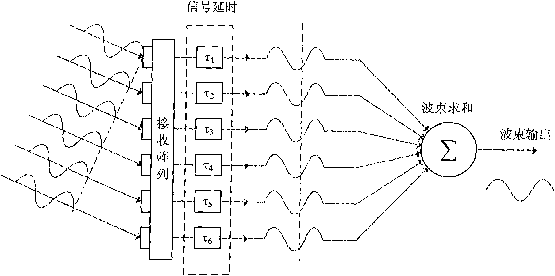
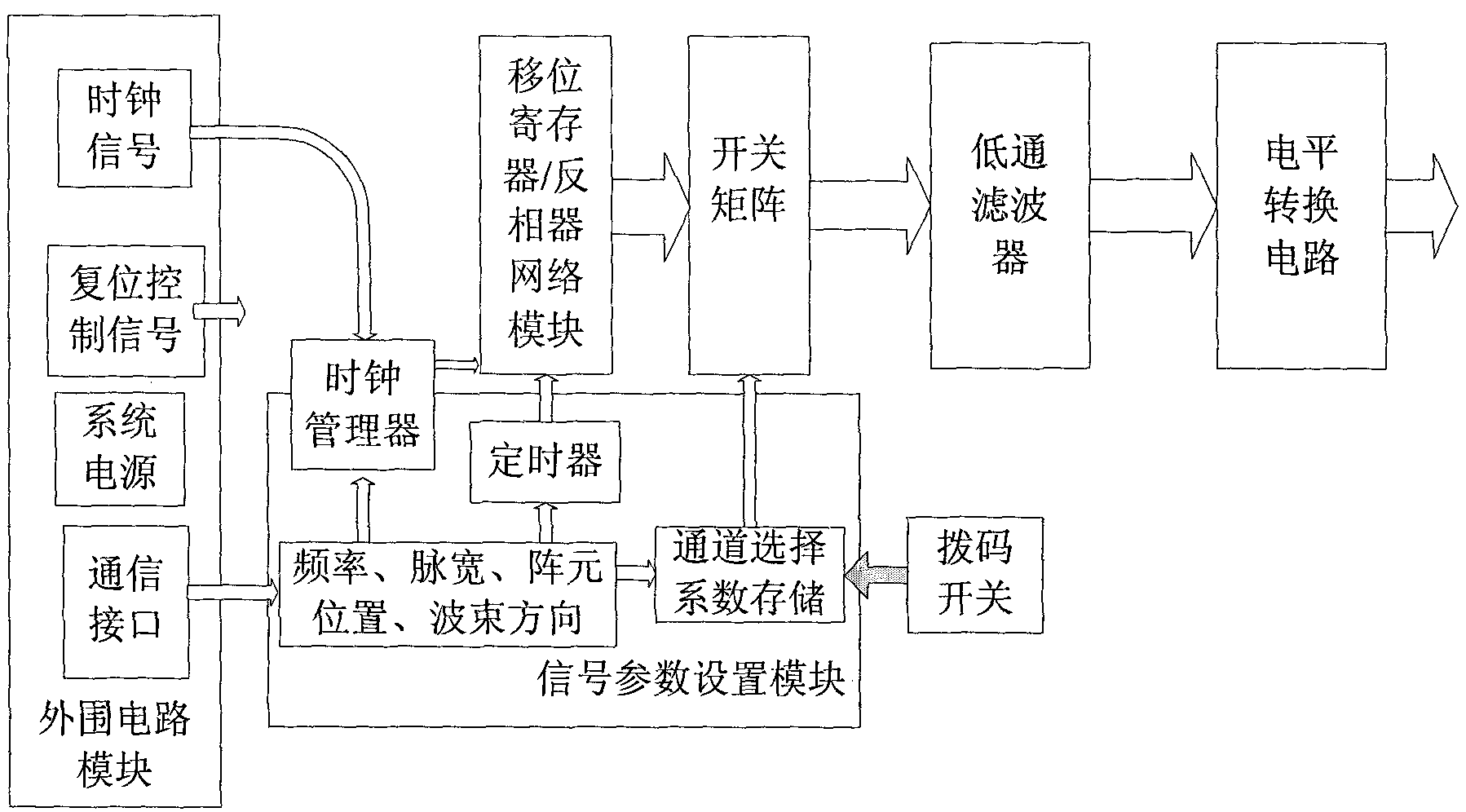
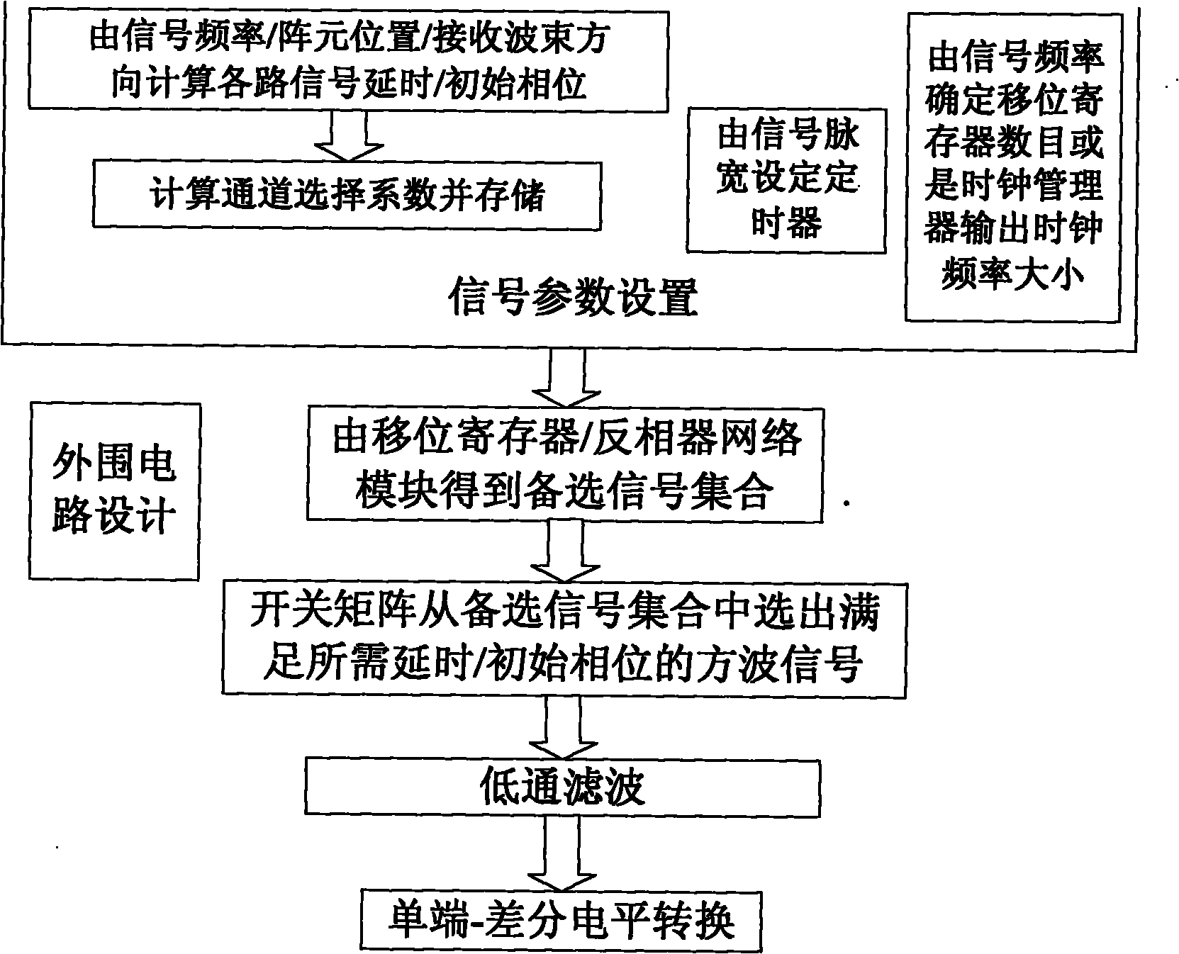
[0081] See attached picture. The analog generation method of the output signal of the multi-channel receiving array in this embodiment is described for the application environment of the sonar system, but the principle is also similar in the radar and communication systems. The specific implementation examples of the present invention are only for demonstration, and are not intended to limit the protection scope of the present invention.

[0082] This embodiment can produce 128-channel differential output, the phase consistency between each channel is good, the frequency is 165 / 195khz, the position of the array element is determined by the U-shaped / Uniform Linear (ULA) array, and the direction of the receiving beam is plus or minus 0 / 30 / 45 / 60 / 90 degree, pulse width 10ms sonar receiving array output signal. The module diagram of the multi-channel...


PUM


Abstract

The invention discloses a multichannel array signal generating method and a device. The device comprises a signal parameter setting module, a shift register, a phase inverter network module, a switch matrix, a low pass filter and a level switch circuit, wherein the signal parameter setting module is used for realizing the selection of signal frequency/ pulse width/ array element position/ wave beam forming direction; the shift register and the phase inverter network module are used for generating multiple paths of delayed/ initial phase equidifferent square signals of which the frequency is f=fclk/2N, wherein fclk is clock signal frequency, and N is the number of the shift register; the switch matrix is used for selecting the square signal with corresponding delay/ initial phase from a square signal assembly according to the needed signal parameter; the low pass filter is used for shaping multiple paths of square signals to obtain multiple paths of sine wave signals; and the level switch circuit is used for carrying out level switch on multiple paths of sine wave signals. The invention is suitable for simulating the formation of a transmitting/ receiving signal by a single-frequency pulse signal wave beam, has artful design and has the advantages of convenient realization, small volume, low cost, low energy consumption and multiple paths.

Description

technical field [0001] The invention relates to the technical fields of sonar, radar and wireless communication, in particular to the related technology of receiving / transmitting beam formation in a multi-channel transducer / antenna array system. Background technique [0002] Beamforming usually works in conjunction with acoustic wave transmitting / receiving transducer arrays or electromagnetic wave transmitting / receiving antenna arrays, and is widely used in sonar, radar, communication and other fields. Beamforming includes two parts: beamforming on received signals and beamforming on transmitted signals: [0003] (1) Beamforming the received signal: In order to make the transducer / antenna array strengthen the signal arriving from one or more specific directions, the basic beamforming method delays the signal received by each array element according to the beam direction. , then add the time-delay-aligned signals to obtain a beam output pointing to a specific direction. Suc...

Claims


Application Information

Patent Timeline
IPC IPC(8): G01S7/00
Inventor 徐文吴光颉杨志国
Owner ZHEJIANG UNIV
Why Eureka
Try Eureka