
Charging circuit for lead acid batteries with high power factors

A high power factor, lead-acid battery technology, applied in battery circuit devices, high-efficiency power electronic conversion, circuit devices, etc., can solve the problems of no power factor correction compensation, complex circuit structure, poor power quality, etc., and achieve high conversion. Efficiency, simple circuit structure, and the effect of improving utilization

Active Publication Date: 2010-08-18
无锡新畅电子有限公司
View PDF5 Cites 8 Cited by
  • Summary
  • Abstract
  • Description
  • Claims
  • Application Information

AI Technical Summary

Problems solved by technology

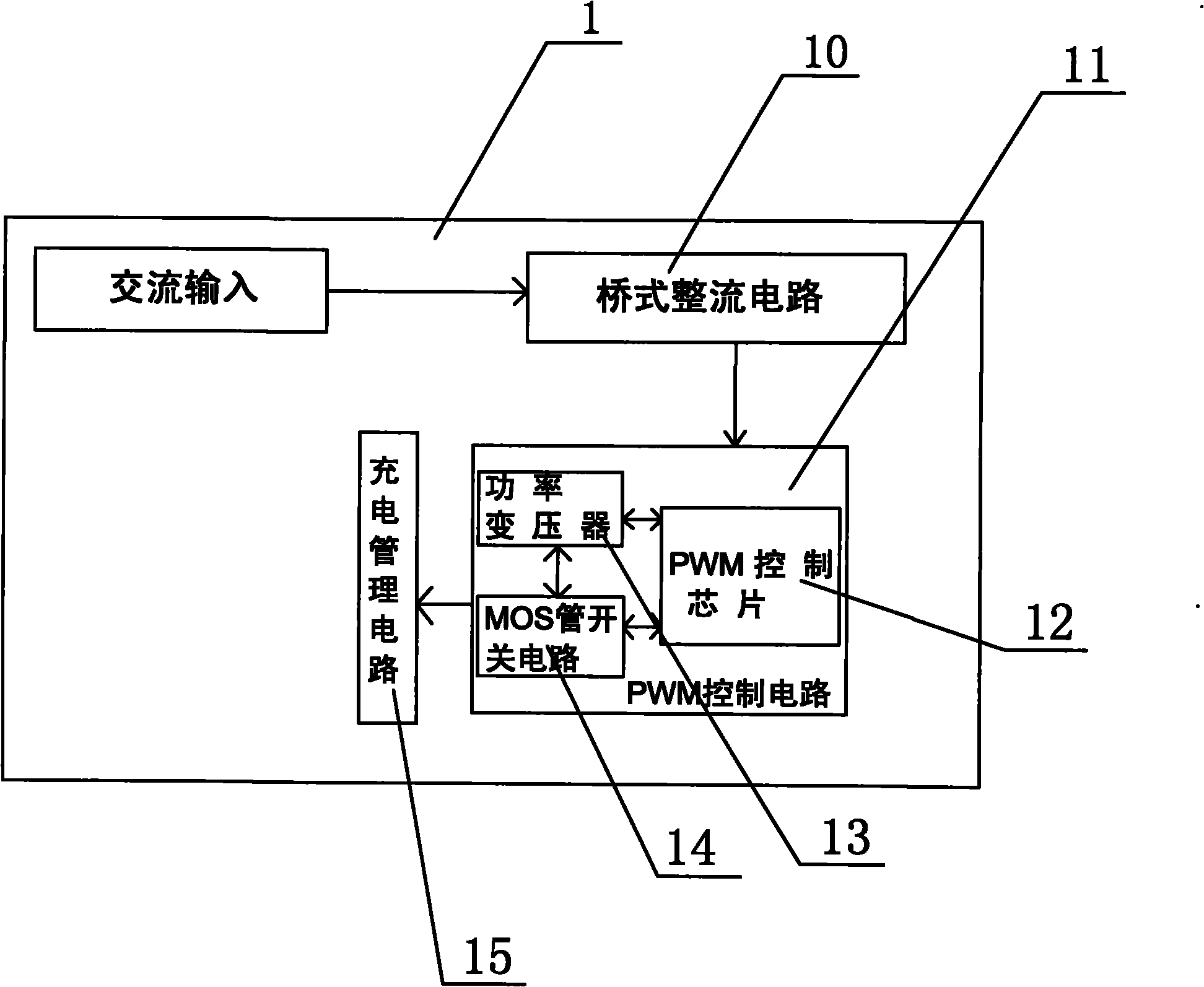
[0003] As we all know, the lead-acid battery charger for electric vehicles is one of the necessary accessories for electric vehicles, and it is also one of the key accessories for electric vehicles. Please refer to figure 1 as shown, figure 1 It is a block diagram of a traditional electric vehicle lead-acid battery charging circuit. The traditional electric vehicle lead-acid battery charging circuit 1 is AC input to a bridge rectifier circuit 10, and the output end of the bridge rectifier circuit 10 is connected to the input of a PWM control circuit 11. terminal, the PWM control circuit 11 includes a PWM control chip 12, the PWM control chip 12 is connected to a power transformer 13 and a MOS transistor switch circuit 14, and the output terminal of the PWM control circuit 11 is connected to a charging management circuit 15, but the traditional electric motor The charging circuit of the lead-acid battery of the car has no power factor correction compensation, and the power quality is poor
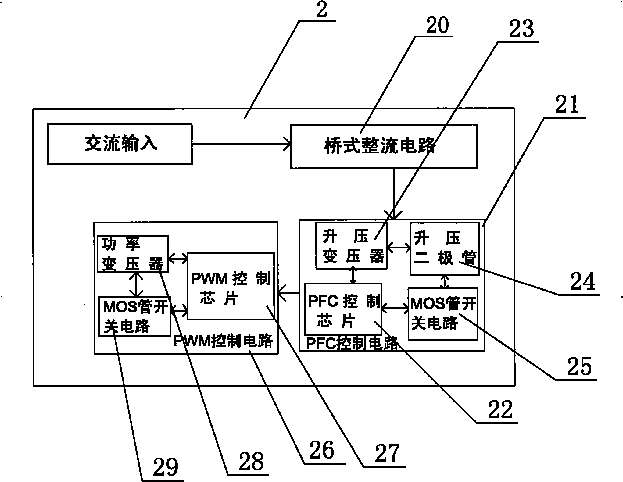
[0004] At present, there are many ways to improve the power factor. High-frequency PFC technology has an absolute advantage in existing applications because of its outstanding advantages, various circuit forms, and a complete range of integrated control devices. In fact, electric vehicle charging circuits are essentially It is composed of two parts, the power conversion part (switching power supply part) and the charging control part. The power conversion part, that is, the switching power supply part is the core of the charger. Whether the charger is reliable, the power factor and the efficiency all depend on the switching power supply. section, see figure 2 as shown, figure 2 It is a block diagram of a traditional switching power supply circuit with PFC correction. The traditional switching power supply circuit 2 with PFC correction is input to a bridge rectifier circuit 20, and the output end of the bridge rectifier circuit 20 is connected to a PFC control circuit 21. The PFC The control circuit 21 includes a PFC control chip 22, the PFC control chip 22 is connected to a boost transformer 23, a boost diode 24 and a MOS transistor switch circuit 25, and the output of the PFC control circuit 21 is connected to the input of the PWM control circuit 26 The PWM control circuit 26 includes a PWM control chip 27, and the PWM control chip 27 is connected to a power transformer 28 and a MOS transistor switch circuit 29, but the traditional switching power supply circuit with PFC correction has a complicated circuit structure and high cost Shortcomings

Method used


Image

  • Charging circuit for lead acid batteries with high power factors
  • Charging circuit for lead acid batteries with high power factors
  • Charging circuit for lead acid batteries with high power factors

Examples


Embodiment Construction

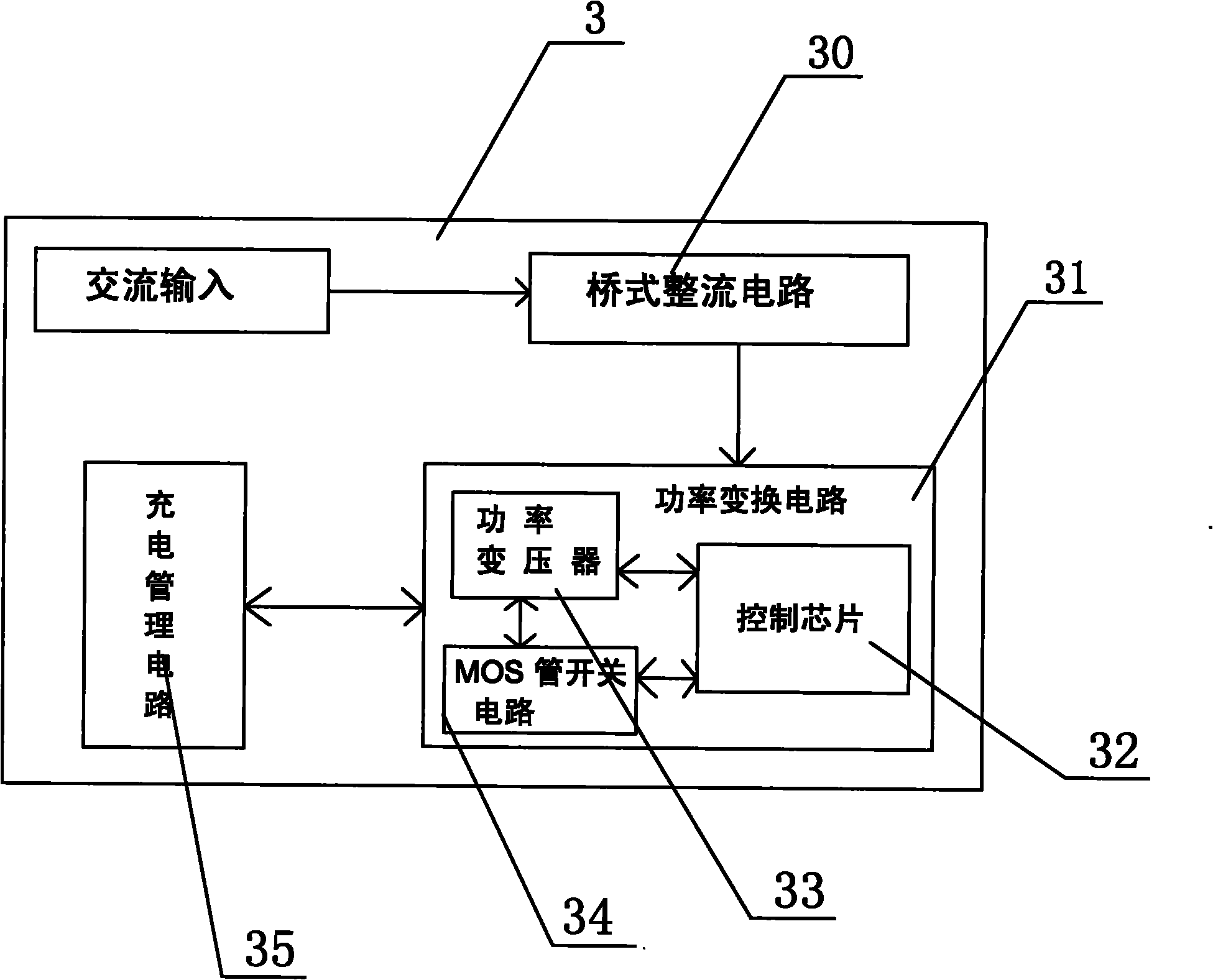
[0018] see image 3 and Figure 4 as shown, image 3 Be the block diagram of high power factor lead-acid battery charging circuit of the present invention, Figure 4 It is a specific circuit diagram of the high power factor lead-acid battery charging circuit of the present invention.

[0019] A high power factor lead-acid battery charging circuit, the high power factor lead-acid battery charging circuit 3 includes a bridge rectifier circuit 30, a power conversion circuit 31 and a charging management circuit 35, and the bridge rectifier circuit 30 is coupled to a power conversion circuit 31, the power conversion circuit 31 is coupled to the charging management circuit 35, the power conversion circuit 31 includes a control chip 32, the control chip 32 is coupled to a power transformer 33 and a MOS tube switch circuit 34, and the model of the control chip 32 is SG6961 Chip U1, which includes pin 1-pin 8, the power transformer T1 includes a transformer primary winding, a transf...


PUM


Abstract

The invention discloses a charging circuit for lead acid batteries with high power factors, which comprises a rectifying circuit, a power conversion circuit and a charging management circuit, wherein the rectifying circuit is coupled with the power conversion circuit; the power conversion circuit is coupled with the charging management circuit; the power conversion circuit comprises a control chip; the control chip is coupled with a power transformer and an MOS tube switching circuit; and the model of the control chip is SG6961. The power conversion circuit of the charging circuit for the lead acid batteries with high power factors realizes the combination of a PFC control circuit and a PWM control circuit, thus the invention has the advantages of simple circuit structure, cost reduction and very high conversion efficiency, and can increase the active power sent by generating equipment and transformation equipment, enable power supply equipment to fully play a role, improve the utilization ratio of an AC power source, reduce the current on power transmission lines, lower voltage drop and power loss on transmission lines and save electric energy.

Description

technical field [0001] The invention relates to a charging circuit, in particular to a lead-acid battery charging circuit with high power factor. Background technique [0002] The power factor (PFC) is an important technical and economic index of the power supply system. While the electrical equipment consumes active power, it also needs a large amount of reactive power to be sent from the power source to the load. The power factor reflects the power consumption of the electrical equipment. The ratio of the reactive power required while consuming a certain amount of active power, the useful power to the total power consumed by the system is the power factor. When the power factor is small, it may reach below 0.6 (this is the case with current chargers), which means More than 40% of the electric energy is lost on the line, and this electric energy will not be recorded on the general watt-hour meter, and the cost incurred is borne by the state, so international standards and n...

Claims


Application Information

Patent Timeline
IPC IPC(8): H02J7/10H02M1/42
CPCY02B70/126Y02B70/10
Inventor 陆勇周晓强
Owner 无锡新畅电子有限公司
Learn More