Self-suspending artificial heart

An artificial heart, self-suspending technology, applied in the field of biomedical engineering, can solve the problems of high manufacturing cost, blood cutting damage, complex structure, etc., and achieve the effects of low cost, simple control, and improved self-balancing

Inactive Publication Date: 2010-08-25
钱逸 +1
View PDF1 Cites 6 Cited by
  • Summary
  • Abstract
  • Description
  • Claims
  • Application Information

AI Technical Summary

Problems solved by technology

[0006] In order to improve the complex structure of the existing artificial heart, the high manufacturing cost, and the mechanism of cutting blood and destroying the blood, the purpose of the present invention is to provide a self-suspending artificial heart, which can meet the needs of clinical medical use, reduce the Destroy blood cells, improve compatibility with blood, reduce R&D and manufacturing costs, and have extremely high self-balancing and self-regulating properties

Method used


Image

  • Self-suspending artificial heart
  • Self-suspending artificial heart
  • Self-suspending artificial heart

Examples


Embodiment 1

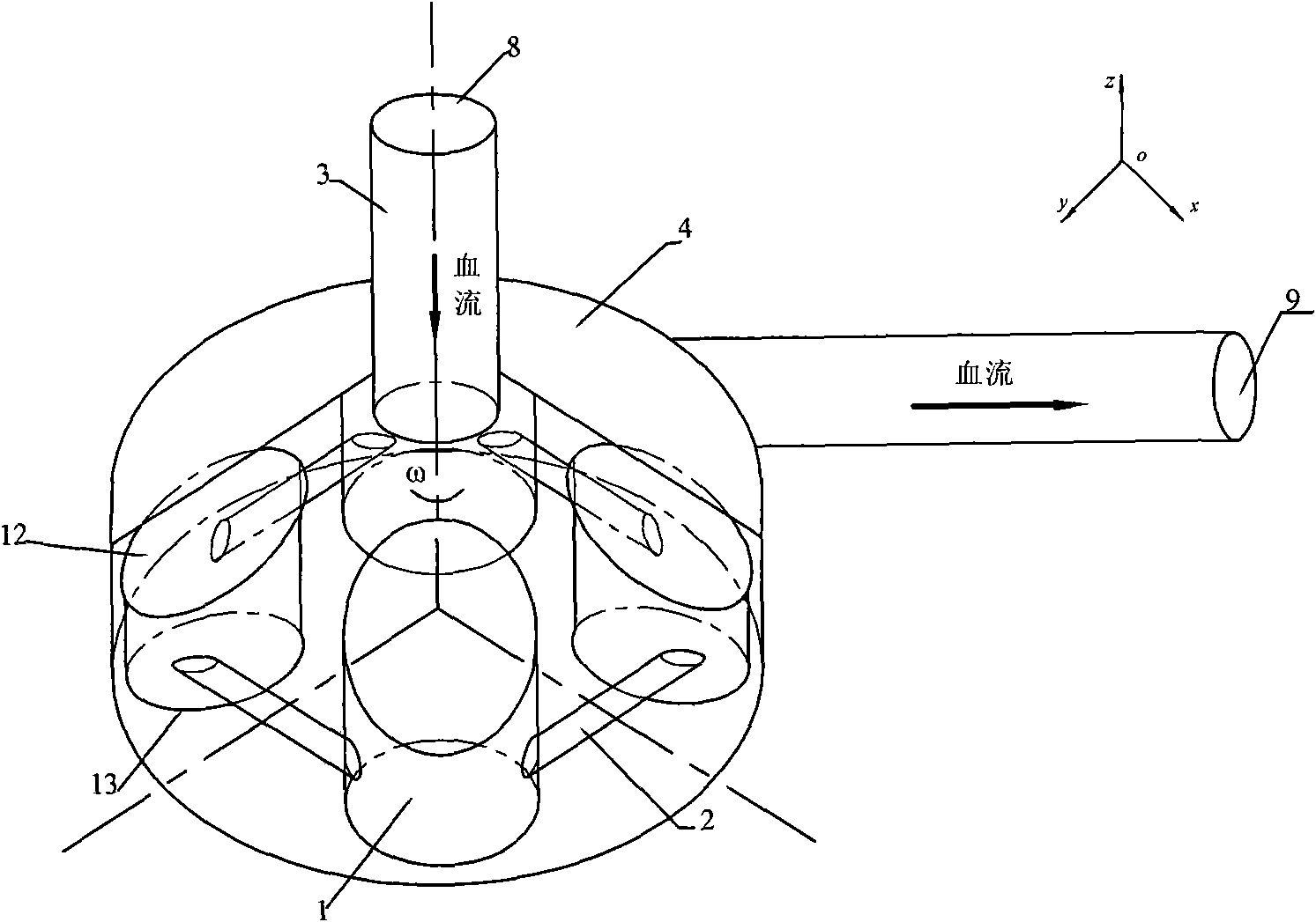
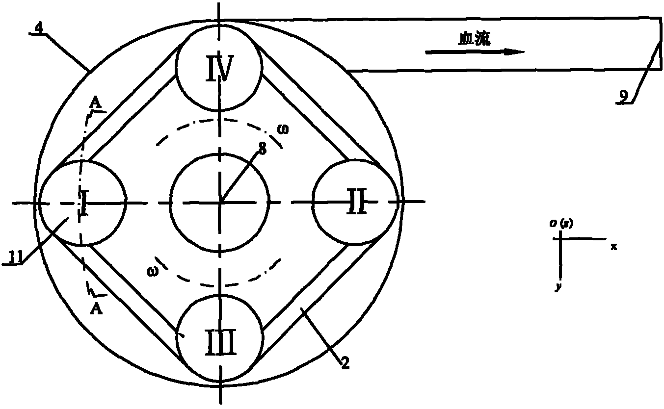
[0029] According to the implementation of the technical scheme shown in Fig. 1-Fig. 5, it can be applied to a new type of artificial heart clinically. A plurality of rotors (or rotor blades) are symmetrically placed in the artificial heart casing 4. The rotor 1 is composed of even-numbered blades and distributed axially symmetrically. The blades are connected and fixed by connecting rods 2. The rotor 1 rotates around the rotation center 3, and the The blood enters the shell from the blood inflow port 8, flows in the shell along the circumferential direction, and outputs blood from the blood outflow port 9 after pressurization, as shown in FIG. 1 .

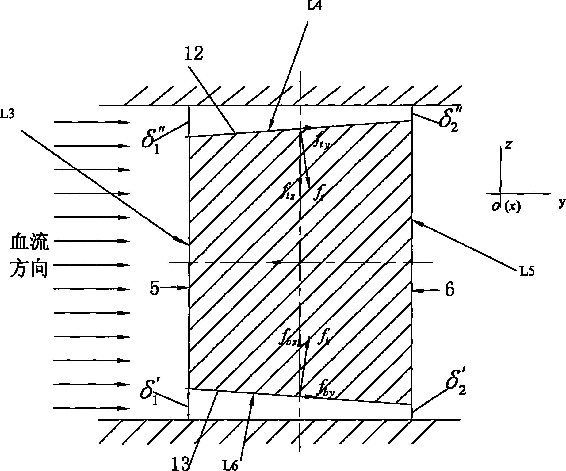
[0030] Each blade is roughly cylindrical, that is, as can be seen from the top view of FIG. 2 , the orthographic projection of its upper and lower slopes is circular.

[0031] Relative to the flow direction of the medium, it includes the upflow surface 5 and the backflow surface 6, the upflow surface refers to the side that flows f...

Embodiment 2

[0043] The difference from Example 1 is that in this example α is 20°, β is 20°, and δ″ 1 =20, δ' 1 =20μm, δ" 2 = 10μm, δ' 2 =5μm, the upper and lower slopes are oblique planes.

Embodiment 3

[0045] The difference from Example 1 is that in this example α is 0°, β is 60°, and δ″ 1 =100, δ' 1 =20μm, δ" 2 =50μm, δ' 2 =15μm, the upper and lower slopes are oblique curved surfaces.


PUM


Abstract

The invention discloses a self-suspending artificial heart. A rotor rotates in a pump body, so fluid is boosted to flow outside along the circumferential direction. The self-suspending artificial heart is characterized in that: the rotor consists of blades of even number; the blades are symmetrically distributed in an axial direction; the blades are connected and fixed by connecting rods; each blade has an approximately cylindrical shape; each blade comprises a flow-receiving surface and a back surface in the flow direction of a medium; and under the condition that the included angles between the upper and lower end surfaces of the rotor and the rotary horizontal plane are more than 0 degree and the condition that the included angle, namely a lower bottom angle, between the lower end surface and the rotary horizontal plane is more than or equal to 0 degree, the clearances between the upper and lower end surfaces of the rotor and the rotor of the pump body decrease progressively from the flow-receiving surface to the back surface. The self-suspending artificial heart has extremely high self-balance and self-adjustment characteristics, can effectively reduce damages to the blood and the formation of thromboses in the artificial heart, strengthen compatibility with the blood, reduce the manufacturing cost, improve the balance of the action forces applied by the blood in the artificial heart onto the rotor in different directions and improve the stability and safety of the rotor in operation.

Description

technical field [0001] The invention belongs to the technical field of biomedical engineering, and in particular relates to a non-contact and bearing-free rotor used for artificial heart blood delivery or other shear-sensitive fluid delivery. Background technique [0002] In recent years, with the rapid development of modern medical technology, higher requirements are put forward for the research and development of medical devices. How to design and develop a new generation of medical devices that are efficient, reliable, and meet the requirements of ergonomic biology is a major challenge for every scientific researcher. topic. In order to transport blood or other shear-sensitive liquids, researchers in the field of cardiovascular medical devices are constantly improving to make the blood pump body smaller and more reliable, and to minimize the adverse effects on the transport medium. [0003] Rotary blood pumps have been used in heart surgery to a certain extent, and can p...

Claims


Application Information

Patent Timeline
IPC IPC(8): A61M1/12
Inventor 钱逸严志焜
Owner 钱逸
Why Eureka
Try Eureka