
Mixed excitation permanent magnet flux switching motor

A technology of magnetic flux switching motor and hybrid excitation, which is applied to the static parts of the magnetic circuit, the rotating parts of the magnetic circuit, the shape/style/structure of the magnetic circuit, etc. Research and application of occasions, limitation of magnetic regulation range, etc., to achieve the effects of small copper loss of electric excitation, low harmonic content of flux linkage, and simple structure

Inactive Publication Date: 2011-09-07
CHANGZHOU INST OF TECH
View PDF0 Cites 0 Cited by
  • Summary
  • Abstract
  • Description
  • Claims
  • Application Information

AI Technical Summary

Problems solved by technology

[0004] In the permanent magnet flux switching motor, there is only a permanent magnet magnetic potential source, and there is an inherent problem that the air gap magnetic field is difficult to adjust. Although the magnetic field can be adjusted through the armature current vector control, the magnetic field adjustment range has great limitations. Limits the research and application in wide-speed adjustable drive system

Method used


Image

  • Mixed excitation permanent magnet flux switching motor
  • Mixed excitation permanent magnet flux switching motor
  • Mixed excitation permanent magnet flux switching motor

Examples


Embodiment Construction

[0024] The present invention will be further described below in conjunction with accompanying drawing:

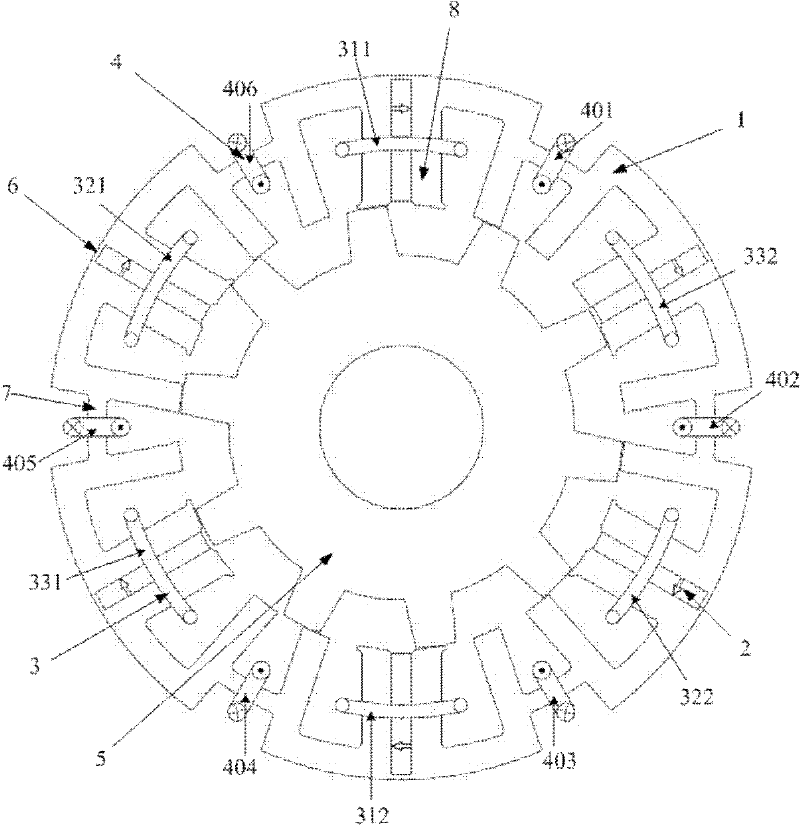
[0025] Such as figure 1 As shown, the hybrid excitation permanent magnet flux switching motor of the present invention includes a stator 1 and a rotor 5, and the rotor 5 with 10 salient poles is located inside the stator 1; Permanent magnets: Three-phase armature windings 3, single-phase field windings 4 and six permanent magnets 2 are arranged on the stator 1.

[0026] The stator 1 includes: 12 U-shaped stator cores, and the first iron core connecting magnetic bridge 6 and the second iron core connecting magnetic bridge 7 which are connected circularly to each U-shaped iron core in turn; the two U-shaped arms of each U-shaped iron core are stator teeth 8 , so the number of stator teeth 8 is four times the number of permanent magnet blocks; the U-shaped iron core of the stator is connected to the magnetic bridge through the iron core to form a whole, which is convenient fo...


PUM


Abstract

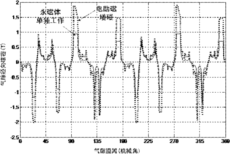
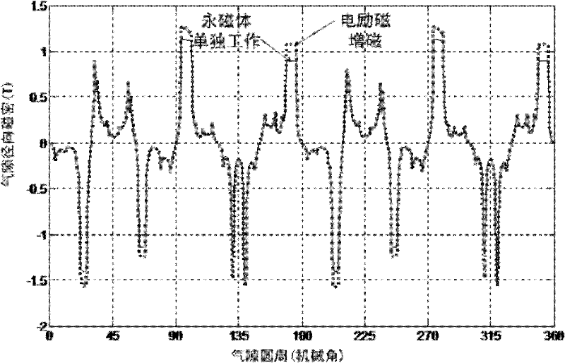
The invention discloses a mixed excitation permanent magnet flux switching motor which comprises permanent magnets, three-phase armature windings and single-phase excitation windings, wherein the single-phase excitation windings are arranged on a stator, the tooth number of the stator is 4 times number of permanent magnets; and a rotor is in a salient pole structure and has no windings or permanent magnets, thereby having high mechanical strength and being suitable for high-speed operation. An air-gap field comprises an electric excitation magnetic field generated by the excitation windings and a magnetic field generated by the permanent magnets, and is flexibly adjusted by changing an excitation current. An electric excitation magnetic line of force is closed by using an iron core connecting magnetic bridge, which is beneficial to reducing the electric field ampere-turns and lowering the electric excitation copper loss. The armature windings and the excitation windings are distributed in different stator grooves at intervals, which is beneficial to increasing the self-inductance of the armature windings and the mutual inductance of the windings and effectively inhibiting the short circuit current of a motor.

Description

technical field [0001] The invention relates to the field of stator hybrid excitation motors, in particular to a hybrid excitation type permanent magnet flux switching motor. Background technique [0002] Permanent magnet synchronous motors use permanent magnet materials instead of excitation windings. Compared with traditional DC motors, asynchronous motors and switched reluctance motors, there is no excitation copper loss, and it has the advantages of high power density and high efficiency. However, since the permanent magnets are placed on the rotor, corresponding fixing devices need to be installed on the rotor, which causes cooling difficulties, and the temperature rise may eventually lead to irreversible demagnetization of the permanent magnets, which limits the output of the motor. [0003] The doubly salient pole permanent magnet motor proposed by Lipo in 1992, the flux reversal motor proposed by I. Boldea in 1996, and the flux switching permanent magnet motor propos...

Claims


Application Information

Patent Timeline
Patent Type & Authority Patents(China)
IPC IPC(8): H02K1/17H02K1/14H02K1/24
Inventor 许泽刚谢少军
Owner CHANGZHOU INST OF TECH
Learn More