Supercharge Your Innovation With Domain-Expert AI Agents!

Methods and apparatus for cooling syngas within gasifier system

一种合成气、合成气冷却器的技术,应用在激冷环领域,能够解决表面不均匀、受限空间等问题

Active Publication Date: 2010-09-01
AIR PROD & CHEM INC
View PDF5 Cites 20 Cited by
  • Summary
  • Abstract
  • Description
  • Claims
  • Application Information

AI Technical Summary

Problems solved by technology

If insufficient water is supplied to the chill rings, the water flow from such chill rings may be uneven to the surface to be cooled
Additionally, the use of such chill rings may be limited by the water available and / or the space available for positioning the chill rings

Method used


Image

  • Methods and apparatus for cooling syngas within gasifier system
  • Methods and apparatus for cooling syngas within gasifier system
  • Methods and apparatus for cooling syngas within gasifier system

Examples


Embodiment Construction

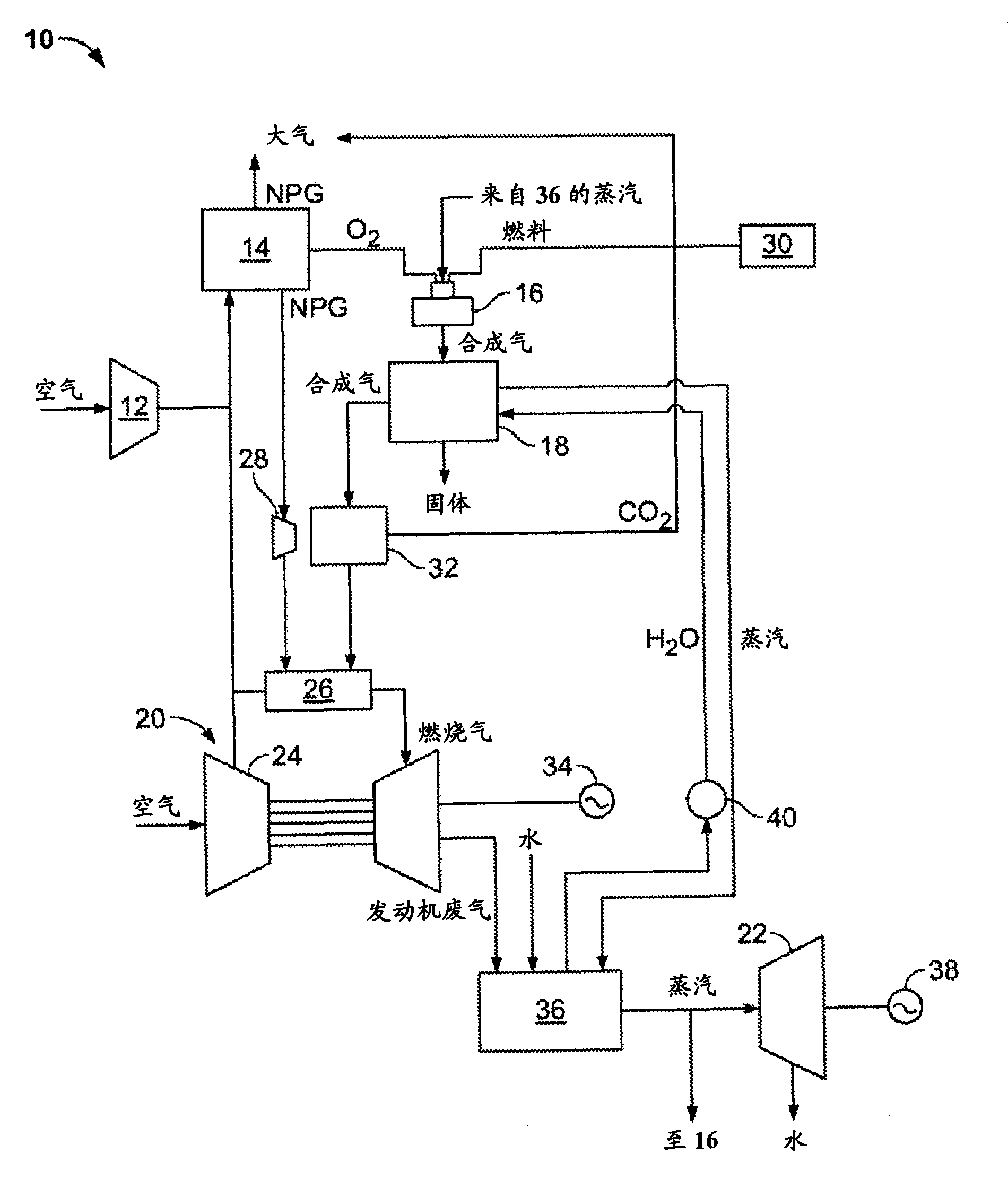
[0012] figure 1 is a schematic diagram of an exemplary integrated gasification combined cycle (IGCC) power generation system 10 . The IGCC system 10 generally includes a main air compressor 12, an air separation unit (ASU) 14 coupled in flow communication to the compressor 12, a gasifier 16 coupled in flow communication to the ASU 14, a gasifier 16 coupled in flow communication to the gas A syngas cooler 18 of the carburetor 16 , a gas turbine engine 20 coupled in flow communication to the syngas cooler 18 , and a steam turbine 22 coupled in flow communication to the syngas cooler 18 .

[0013] In operation, compressor 12 compresses ambient air, which is then channeled to ASU 14 . In the exemplary embodiment, compressed air from gas turbine engine compressor 24 is supplied to ASU 14 in addition to compressed air from compressor 12 . Alternatively, compressed air from gas turbine engine compressor 24 is supplied to ASU 14 instead of compressed air from compressor 12 . In the...


PUM


Abstract

A method for operating a syngas cooler is provided. The method includes channeling a flow of syngas into an annular cooling chamber having a longitudinal axis, injecting a cooling fluid into a manifold such that the cooling fluid is channeled substantially circumferentially about the annular cooling chamber, and discharging the cooling fluid from the manifold such that the cooling fluid contacts a surface of the cooling chamber at a predetermined angle relative to the axis of the cooling chamber.

Description

technical field [0001] The present invention relates generally to syngas coolers within gasifier systems, and more particularly, to quench rings for use with syngas coolers. Background technique [0002] Some known syngas coolers cool the syngas, fly ash particles and slag inclusions in the syngas as it is cooled by radiative and convective heat exchange in an array of tubes. By rapidly reducing the bulk temperature of the syngas, slag and / or particles, some suspended slag and / or particles can be deposited from the syngas onto the tube surfaces. Other slag droplets or particles are cooled and discharged from the lower section of the syngas cooler tube region along with the cooled syngas. In such boilers, solidified slag inclusions, cooled particles and cooled syngas are removed at the lower end of the downflow syngas cooler tube region. [0003] Other known syngas coolers use a chilling system to chill the syngas, slag inclusions and particulates contained therein with a c...

Claims


Application Information

Patent Timeline
Patent Type & Authority Applications(China)
IPC IPC(8): C10J3/82
CPCC10J3/86Y02E20/18C10K1/04F28F13/06C10J2300/165C10J2300/0973C10J2300/1675C10J3/06C10J3/845C10J3/463C10J3/466C10K1/101C10J2300/1838C10J3/84C10J2300/1884F28C3/06C10J2300/1678C10J2300/1671C10J2300/0959
Inventor J·H·B·科里Y·S·莫辛
Owner AIR PROD & CHEM INC
Features
  • R&D
  • Intellectual Property
  • Life Sciences
  • Materials
  • Tech Scout
  • Unparalleled Data Quality
  • Higher Quality Content
  • 60% Fewer Hallucinations
Learn More