
Working vehicle and amount controlling method of working oil thereof

A technology for operating vehicles and hydraulic oil, which is applied to control devices, vehicle components, mechanically driven excavators/dredgers, etc., can solve problems such as power loss, and achieve the effect of improving operating efficiency and increasing hydraulic oil volume

Inactive Publication Date: 2010-09-01
KOMATSU LTD
View PDF2 Cites 10 Cited by
  • Summary
  • Abstract
  • Description
  • Claims
  • Application Information

AI Technical Summary

Problems solved by technology

Even in a work vehicle with such a special brake pedal, in order to transmit power to the work equipment side, the special brake pedal is operated when the clutch is operated, so there is a problem of power loss due to braking

Method used


Image

  • Working vehicle and amount controlling method of working oil thereof
  • Working vehicle and amount controlling method of working oil thereof
  • Working vehicle and amount controlling method of working oil thereof

Examples


Embodiment 1

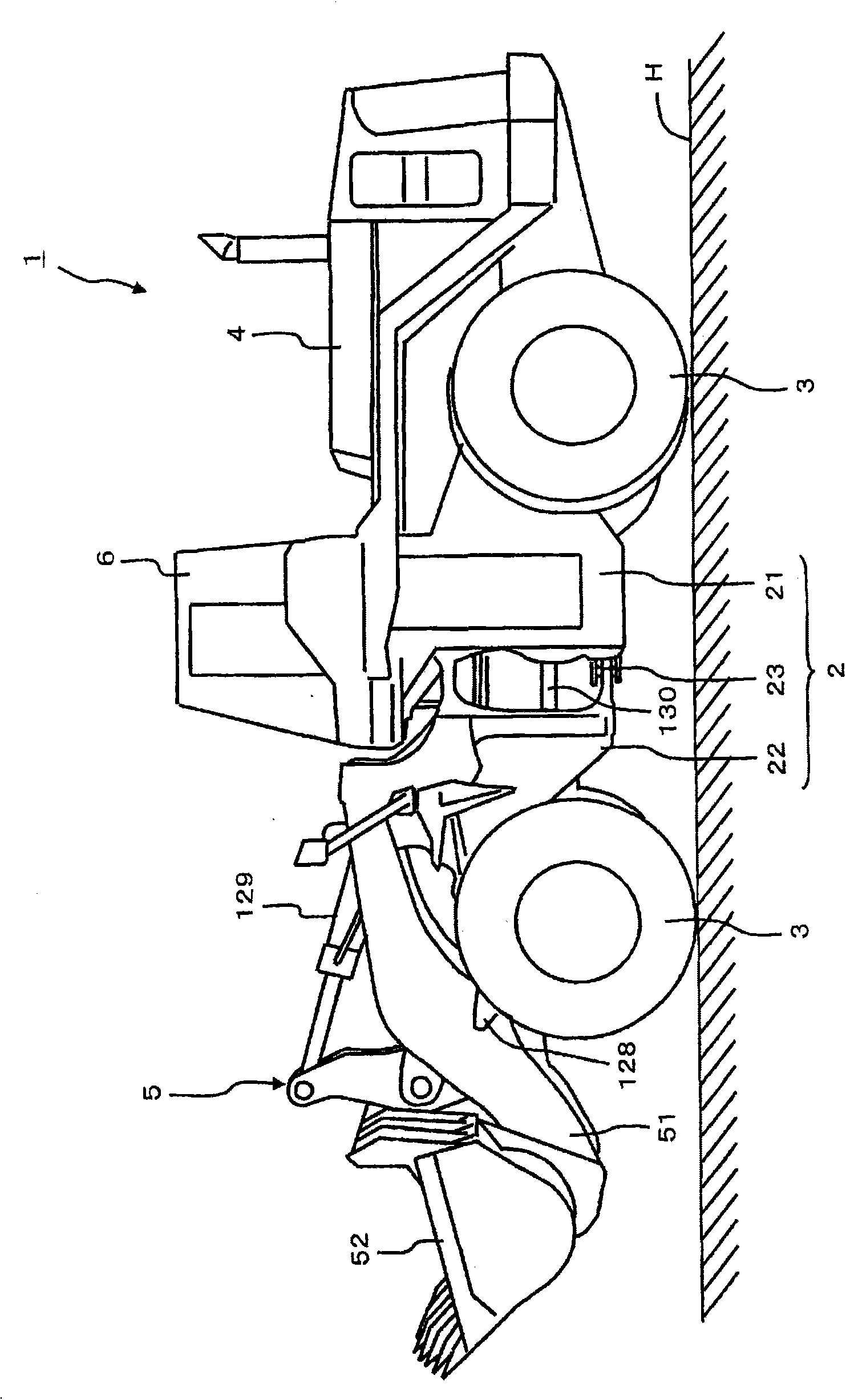
[0052] Next, a case where an embodiment of the present invention is applied to a wheel loader as a work vehicle will be described as an example. However, this embodiment can also be applied to work vehicles other than wheel loaders.

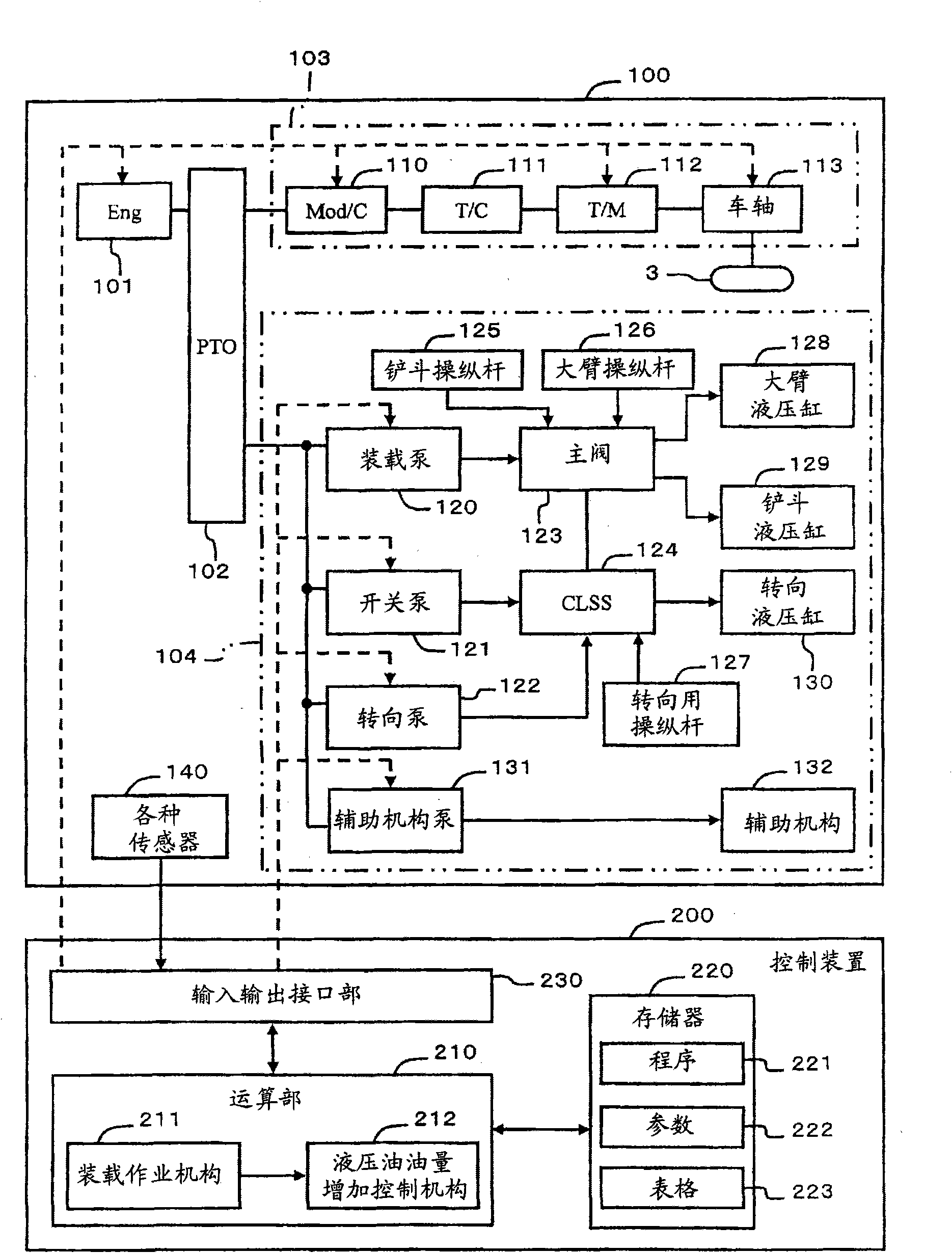
[0053] figure 1 It is an explanatory diagram schematically showing the overall structure of the wheel loader. The wheel loader is roughly divided into a mechanical structure 100 and a control structure (hereinafter referred to as a controller) 200 . First, the mechanical structure 100 will be explained, and then the controller 200 will be explained.

[0054] The mechanical structure 100 has, for example, an engine 101 , an output distributor (PTO: Power Take Off) 102 for distributing the output of the engine 101 to a traveling system 103 and a hydraulic system 104 , and a traveling system 103 for driving the wheel loader 1 , And the hydraulic device system 104 mainly used to drive the working device 5 .

[0055] refer here image 3 . image...

Embodiment 2

[0110] Next, a modified example of the processing for detecting loading work will be described. The following embodiments correspond to modified examples of the first embodiment. exist Figure 11 In the shown second embodiment, the controller 200 determines whether the boom joystick 126 is operated in the upward direction (S10) and whether the boom angle θb is greater than the specified angle θ1 (S11). When both conditions are satisfied, It is determined that the loading operation is being performed (S14).

[0111] The present embodiment constituted in this way also obtains the same effects as those of the first embodiment described above. In this embodiment, since the process of detecting the loading operation is simpler than that of the first embodiment, the control program can be simplified compared with the first embodiment.

Embodiment 3

[0113] exist Figure 12 In the third embodiment shown, the controller 200 respectively determines the first condition (S10) and the fourth condition (S13) described in the first embodiment, and when the two conditions are satisfied, it is determined that the loading operation is in progress (S14). The present embodiment configured in this way also obtains the same effects as those of the second embodiment.


PUM


Abstract

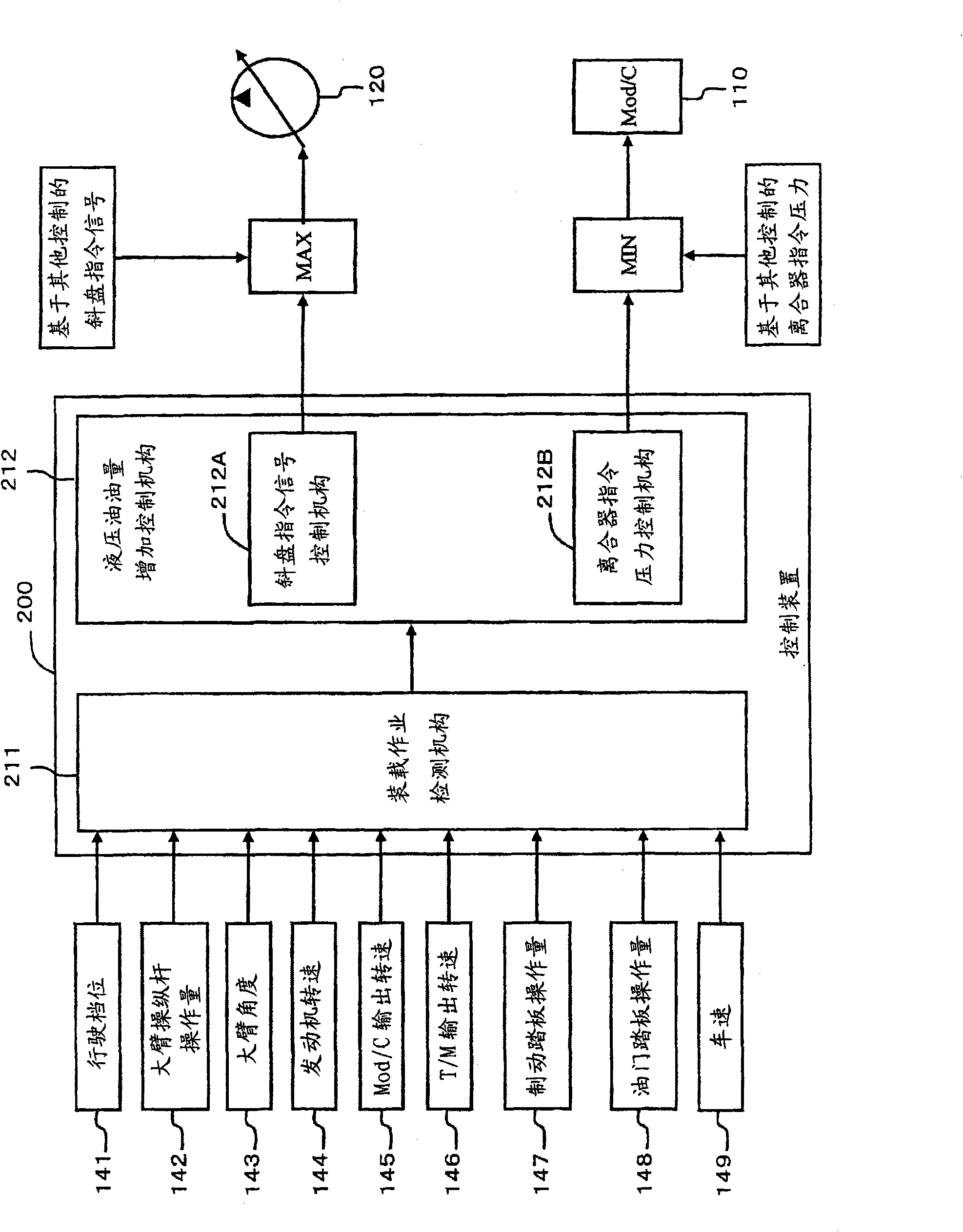
The invention provides a working vehicle and an amount controlling method of working oil thereof. Provided is a working vehicle, which is improved in its operability and its working efficiency at a loading work time. Loading work detecting means (211) detects the start of the loading work by a working machine, on the basis of at least two of a plurality of parameters of whether or not a boom lever (126) is operated in an upward direction, whether or not a boom is brought to a preset position, whether or not the boom angle is less than an upper limit angle, whether or not the velocity ratio at a brake-off time is higher than a predetermined value, whether or not the gear stage is at a predetermined one, whether or not the running range is switched from backward to forward, and whether or not the angular velocity of the boom is at a predetermined value. Oil quantity increase control means (212) either increases the discharge quantity of a loader pump (120) or feeds the working oil from a switch pump (121) to a boom cylinder (128), thereby to feed the boom cylinder (128) with more working oil.

Description

technical field [0001] The invention relates to a working vehicle and a method for controlling the amount of hydraulic oil of the working vehicle. Background technique [0002] For example, in a wheel loader which is a work vehicle, engine output is used as power for work and power for travel. In a wheel loader, a load such as sand and soil is scooped up by the bucket of the work equipment, and the bucket is lifted by the boom to load the load into a truck bed or the like. Work efficiency can be increased by rapidly raising the full bucket. [0003] Therefore, in the prior art, when carrying out loading work, the operator simultaneously operates the brake pedal and the accelerator pedal. As a result, while running at a low speed, the rotational speed of the hydraulic pump is increased to increase the amount of hydraulic oil supplied to the work implement (Patent Document 1). In addition, the technique of controlling the engagement degree of the clutch according to the rot...

Claims


Application Information

Patent Timeline
IPC IPC(8): E02F3/43B60K17/28E02F9/22
CPCE02F9/2235E02F9/2242E02F9/2079E02F9/2253
Inventor 斋藤芳明
Owner KOMATSU LTD
Learn More