
Sludge agitator tank

A technology for stirring tanks and sludge, applied in the direction of dehydration/drying/thickened sludge treatment, etc., to achieve the effect of low operating cost, simple structure, and extended flow lines

Inactive Publication Date: 2011-09-28
江苏思澳环保科技有限公司
View PDF0 Cites 0 Cited by
  • Summary
  • Abstract
  • Description
  • Claims
  • Application Information

AI Technical Summary

Problems solved by technology

Among them, adding coagulant to sewage cement for mixing is a key step of this method. It is required that the mixed sewage cement should be uniformly dosed. On the basis of meeting the requirements, the amount of dosing must be reduced as much as possible to save costs. There are many substances, and the liquid state is constantly evaporating. It is necessary to ensure that the sewage cement after dosing is not hardened, so usually a mixer with enough solidification cannot meet the requirements.

Method used


Image

  • Sludge agitator tank
  • Sludge agitator tank
  • Sludge agitator tank

Examples


Embodiment Construction

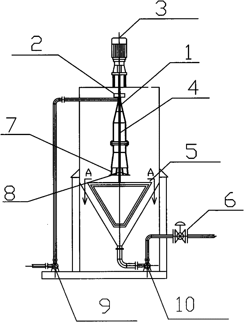
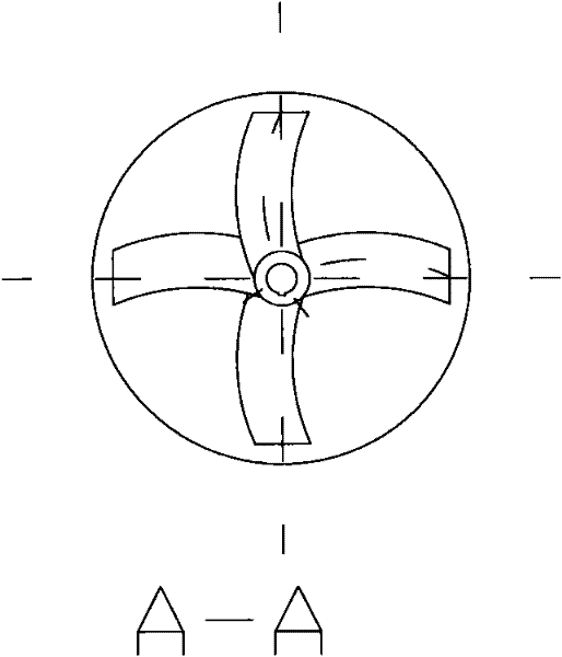
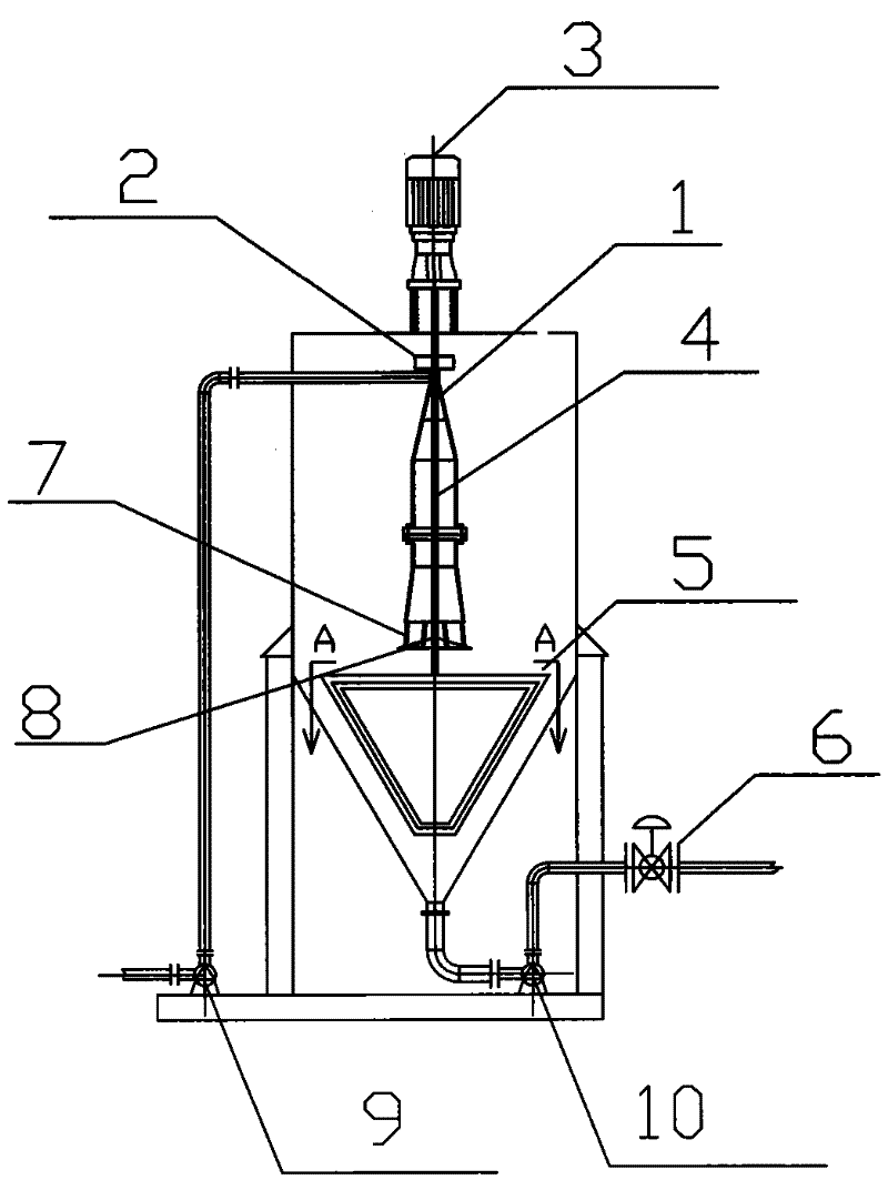
[0015] Such as figure 1 , The sludge mixing tank is mainly composed of a tank body, a central reactor 1, an oil collecting ring 2, a motor 3, and a stirring paddle 5, wherein:

[0016] The motor 3 is installed on the top of the tank, and its output shaft extends to the bottom of the tank. A fixed central reactor 1 is coaxially installed in the tank. The central reactor 1 is a thin-walled and hollow stepped truncated cone. The bottom end is connected to the water retaining plate 8 through several vertical grids 7 . The mouth of the sludge conveying pipe is inserted into the upper part of the central reactor 1 in a horizontal and oblique direction. The oil collecting ring 2 is arranged on the top of the central reactor and communicates with the reaction chamber 4 inside the central reactor. The oil collecting ring 2 is connected with an oil collecting pipe to collect The light oil is exported to the sludge mixing tank; the stirring paddle 5 is installed at the bottom of the out...


PUM


Abstract

The invention discloses a sludge agitator tank, which comprises a tank body, a central reactor, an oil collecting ring, a motor and a stirring paddle, wherein the motor is arranged at the top of the tank body; an output shaft of the motor extends until the bottom in the tank body; a fixed central reactor is coaxially arranged in the tank body; a pipe mouth of a sludge delivery pipe is horizontally and obliquely inserted into the upper part of the central reactor; the hollow oil collecting ring is arranged at the top end of the central reactor and is communicated with the inside of the centralreactor; the oil collecting ring is connected with an oil collecting pipe for outputting the collected light oil out of the tank body; and the stirring paddle is arranged at the bottom end of the output shaft of the motor. The invention has the advantages of simple structure, convenient operation, small size, high degree of automation, less maintenance workload, convenient management, low energy consumption and low operation cost.

Description

technical field [0001] The invention relates to an environmental protection equipment, in particular a sludge mixing tank, which is an important equipment in the sludge dehydration process, and its function is to evenly mix the oil-containing and alcohol-containing sewage cement produced by the development of oil and gas fields, so as to be used for the following The process creates conditions. Background technique [0002] At present, there is no equipment to separate the sludge from the sludge water in the oil-containing and alcohol-containing low-concentration sewage sludge produced by the development of oil and gas fields. It turned out that the oily and alcohol-containing sewage cement produced in the process of oil extraction, gas and oily sewage concentration was pulled to the sludge pond by car. The sewage cement in the sludge pond was naturally dried by the sun to evaporate the water, methanol and water in the sludge. Condensed oil, after evaporation and drying, th...

Claims


Application Information

Patent Timeline
Patent Type & Authority Patents(China)
IPC IPC(8): C02F11/14
Inventor 王建强谭宗强王峰吴树武
Owner 江苏思澳环保科技有限公司
Learn More