Method for operating an internal combustion engine

A technology for internal combustion engines and motor vehicles, which is applied in the direction of internal combustion piston engines, combustion engines, engine starting, etc., and can solve problems such as lack of braking boost and adverse effects of brake booster functions

Inactive Publication Date: 2010-09-08
DR ING H C F PORSCHE AG
View PDF5 Cites 2 Cited by
  • Summary
  • Abstract
  • Description
  • Claims
  • Application Information

AI Technical Summary

Problems solved by technology

Consequently, the pressure accumulator may be emptied to such an extent that the function of the brake booster is adversely affected after a number of br

Method used


Image

  • Method for operating an internal combustion engine
  • Method for operating an internal combustion engine
  • Method for operating an internal combustion engine

Examples


Embodiment Construction

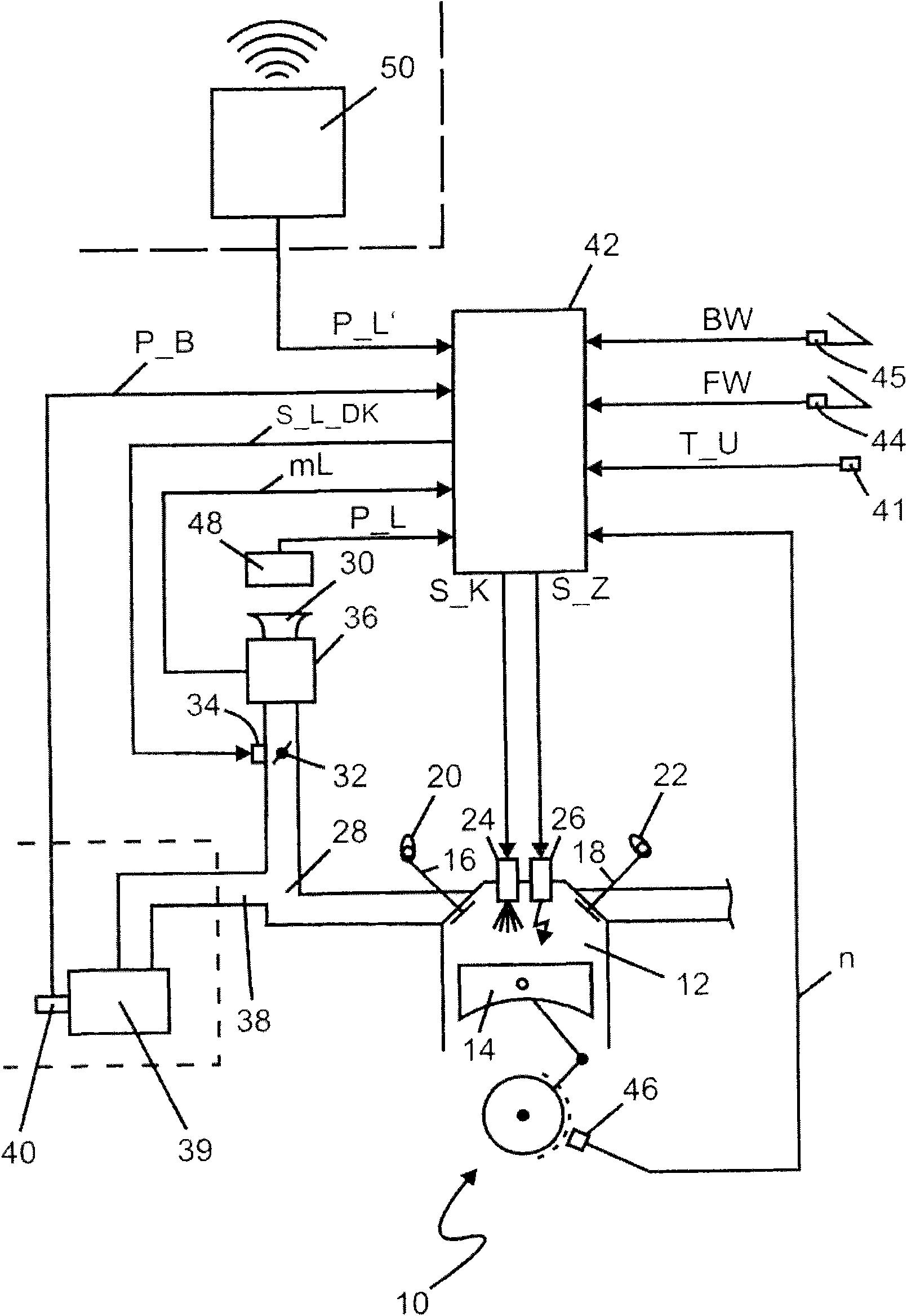
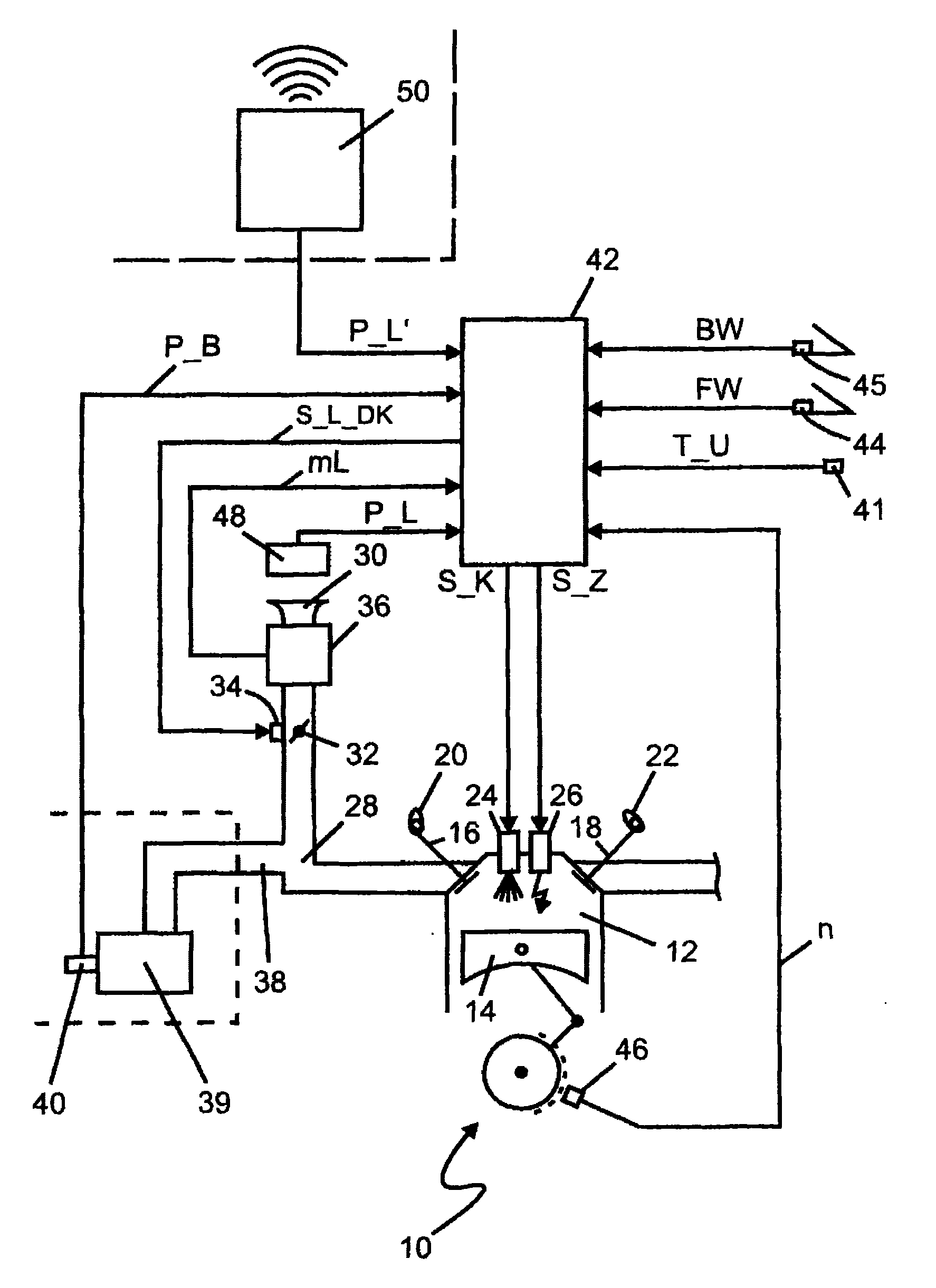
[0017] figure 1 The technical field of the invention is shown. Specifically, figure 1 Shown is an internal combustion engine 10 with a combustion chamber 12 which is movably sealed off by a piston 14 . The change of charge of the combustion chamber 12 is controlled via at least one intake valve 16 and one exhaust valve 18 , which are actuated for this purpose by corresponding actuators 20 , 22 . exist figure 1 In the preferred embodiment, an injector 24 is used to meter the fuel in the air charge into the combustion chamber 22. The resulting fuel and air mixture is ignited by spark plug 26 . The combustion chamber 12 is charged from an intake duct 28 with an intake connection 30 . The intake manifold 28 has a throttle valve 32 , which is operated by a throttle valve adjuster 34 , and an air mass meter 36 . A connecting line 38 branches off from the intake line 28 and leads to a pressure accumulator of a brake booster 39 of the motor vehicle. As an alternative to the ill...


PUM


Abstract

In a method for operating an internal combustion engine (10) in a motor vehicle, the internal combustion engine (10) can be operated with a start/stop system. The motor vehicle has a brake booster (39) which generates an assisting force for assisting a braking force, wherein the brake booster (39) is supplied by an under-pressure in an air inlet pipe of the internal combustion engine (10). In this context, it is detected when the pressure in the brake booster (39) exceeds a threshold value which is determined in an open-loop and/or closed-loop control device (42).

Description

technical field [0001] The invention relates to a method for operating an internal combustion engine in a motor vehicle, wherein the internal combustion engine can be operated via a start / stop system. In this case, the motor vehicle has a brake booster which generates an auxiliary force for assisting the braking force, wherein the brake booster can be supplied with the negative pressure in the intake tract of the internal combustion engine. Alternatively, the required underpressure can also be provided by a vacuum pump which is indirectly or directly driven by the crankshaft of the internal combustion engine. Such mechanical vacuum pumps are used in particular in vehicles whose internal combustion engines are operated according to the diesel method. For both types of vacuum systems, the method according to the invention can be used. Furthermore, a control and / or regulating device and a computer program are also part of the invention. Background technique [0002] In order...

Claims


Application Information

Patent Timeline
IPC IPC(8): F02D29/02F02D11/02F02D11/08
CPCF02B2075/125B60T13/52B60T17/04F02N2200/0807B60T7/18B60T13/72F02N11/084F02N2200/122F02D9/02Y02T10/48F02M35/10229F02N2200/121F02N2200/123Y02T10/40
Inventor T·M·贝尔
Owner DR ING H C F PORSCHE AG
Why Eureka
Try Eureka