
Laser recticle dedusting plant and dedusting method

A technology of laser engraving and dust removal equipment, applied in laser welding equipment, smoke removal, welding equipment and other directions, can solve the problems of pollution energy consumption, incomplete dust removal, loud noise, etc., and achieve the effect of reducing noise

Inactive Publication Date: 2010-09-15
东莞晨真光伏有限公司
View PDF0 Cites 39 Cited by
  • Summary
  • Abstract
  • Description
  • Claims
  • Application Information

AI Technical Summary

Problems solved by technology

[0004] Although the above-mentioned first method of drainage in a closed environment with a high-power exhaust fan can suck away the dust without static electricity, it cannot completely suck away the dust with static electricity adsorbed on the surface of the film and in the wire groove, and the dust removal efficiency is low. On the one hand, it is difficult to form a large enclosed space to generate sufficient airflow; on the other hand, it is necessary to introduce a high-power exhaust fan to realize the dust removal function, and a high-power exhaust fan will cause greater noise pollution and increase energy consumption
[0005] Using the above-mentioned second full-coverage air collection box dust removal method, since the wind direction inlet is set above the amorphous silicon solar panel, it is also necessary to introduce a high-power exhaust fan; The dust removal method of the full-coverage wind box can only absorb the dust in the line space, but cannot absorb the dust adsorbed on the surface of the film and the wire groove due to static electricity, resulting in incomplete dust removal , leading to low dust removal efficiency

Method used


Image

  • Laser recticle dedusting plant and dedusting method
  • Laser recticle dedusting plant and dedusting method
  • Laser recticle dedusting plant and dedusting method

Examples


Embodiment Construction

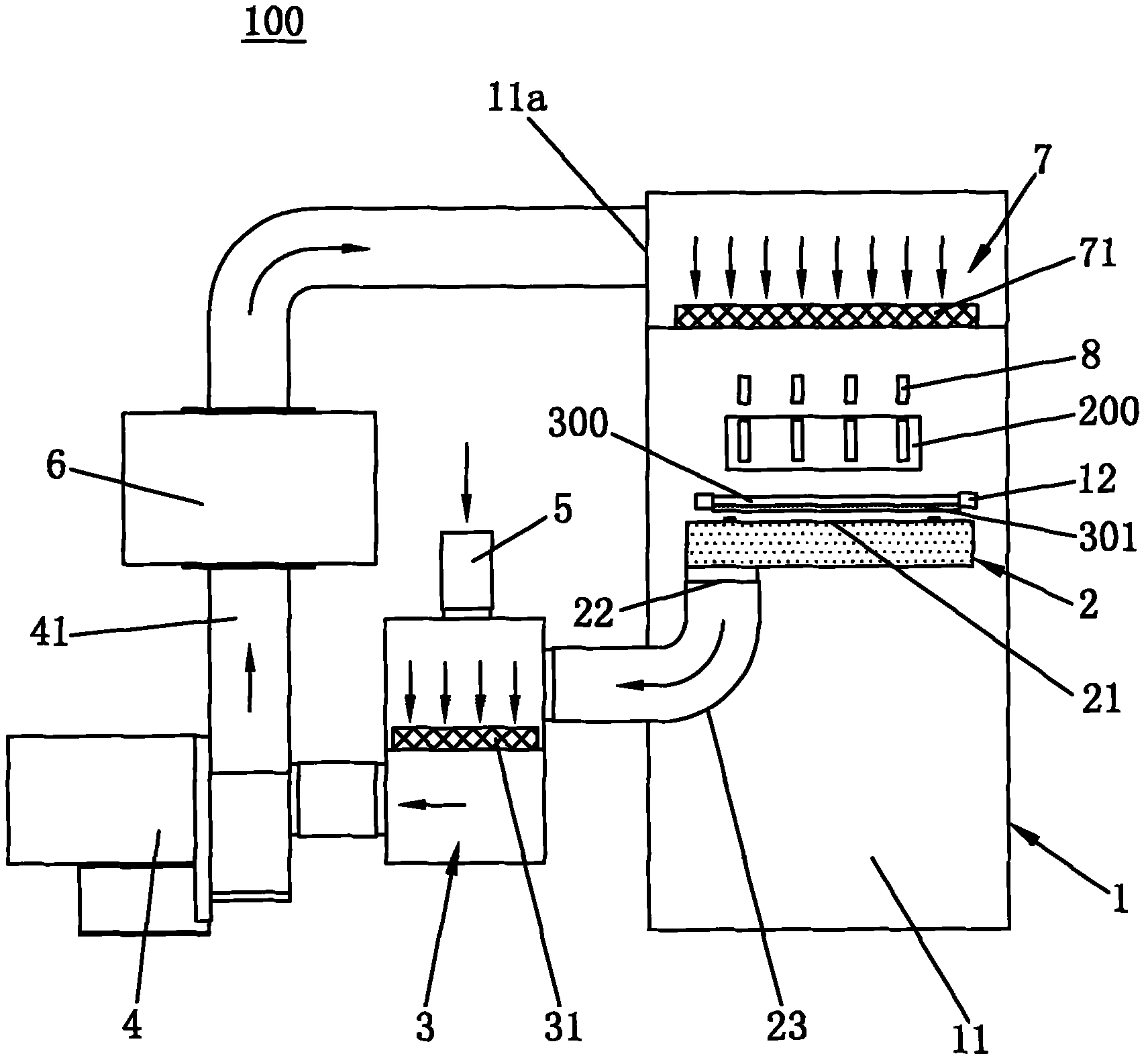
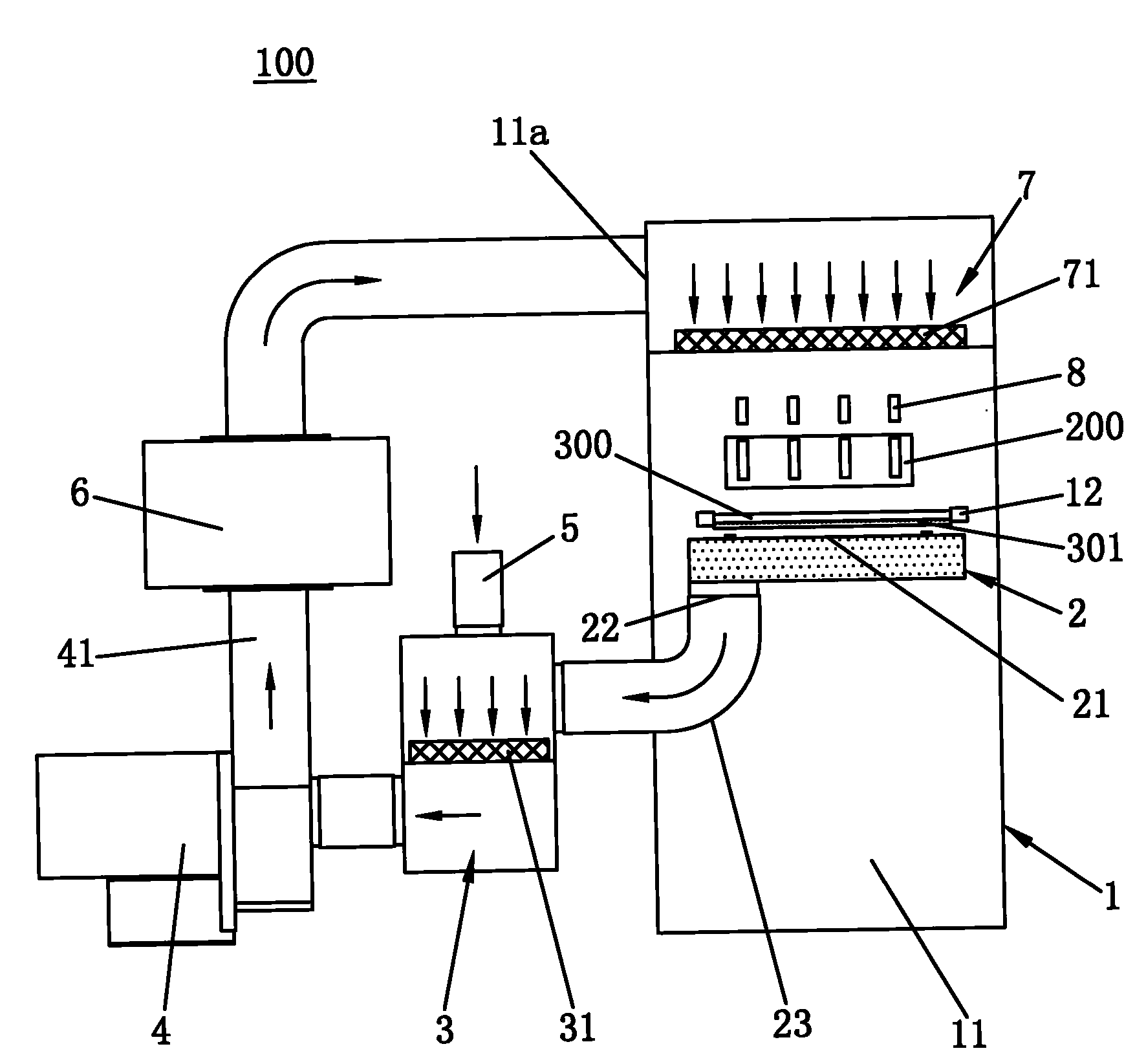
[0017] Such as figure 1 As shown, the laser engraving dust removal equipment 100 of the present invention includes a processing unit 1, a dust suction device 2, a first filter unit 3, a high-pressure exhaust fan 4, an air supply device 5, a constant temperature and humidity unit 6, a second filter unit 7 and Several electrostatic precipitating sticks 8.

[0018] The processing unit 1 includes an inner cavity 11 and a workbench 12, the workbench 12 and the laser generator 200 are placed in the inner cavity 11, and the amorphous silicon solar glass substrate 300 is carried on the workbench 12 The laser generator 200 is placed on the lower surface of the workbench 12 .

[0019] The dust suction device 2 has a dust suction port 21, a dust discharge port 22 and a dust suction pipe 23. The dust suction port 21 is facing the bottom of the workbench 12 and completely covers the amorphous silicon solar glass substrate 300. , the area of ​​the dust suction port 21 is larger than the a...


PUM


Abstract

The invention discloses a laser recticle dedusting plant. The laser recticle dedusting plant comprises a processing unit, a dust exhaust apparatus, a first filter unit, a high pressure exhaust fan and a plurality of electrostatic cleaning bars, wherein the processing unit comprises an inner cavity and an operating platform arranged in the inner cavity; the dust exhaust apparatus comprises a dust suction port and a dust-discharging port, the dust suction port is positioned under the operating platform, the dust-discharging port of the dust exhaust apparatus is communicated with the upper end of the first filter unit, the lower end of the first filter unit is communicated with the suction opening of the high pressure exhaust fan, a first filter net core is arranged between the upper end andthe lower end of the first filter unit, the air outlet of the high pressure exhaust fan is communicated with the inner cavity, and the electrostatic cleaning bars are evenly arranged on the laser generator. The laser recticle dedusting plant has high dedusting efficiency, low noise and little energy consumption. The invention also discloses a laser recticle dedusting method.

Description

technical field [0001] The invention relates to a dedusting device, in particular to a laser scribe dedusting device and method for removing dust generated when a laser generator scribes an amorphous silicon solar glass substrate. Background technique [0002] In the process of solar panel preparation, especially in the preparation process of amorphous silicon solar cell panels, each evaporation (or sputtering, or coating) film layer needs to be laser scribed with a laser generator. During the process of marking, a large amount of electrostatically charged or uncharged dust will be generated and adsorbed or deposited on the marking groove and plate. If the dust generated during the marking process is not cleaned after marking, the next evaporation (or sputtering, or The above-mentioned dust will be covered during the process of film coating), which will cause a short circuit on the circuit layout on the board; at the same time, the dust deposited on the glass surface will al...

Claims


Application Information

Patent Timeline
Patent Type & Authority Applications(China)
IPC IPC(8): B23K26/16B23K26/42
CPCB41M5/26B08B2215/003B23K26/12B41M5/24B08B15/023B23K2201/007B23K26/1405B23K26/127B23K26/142B23K2101/007
Inventor 杨明生蓝劾覃海
Owner 东莞晨真光伏有限公司
Learn More