Current-carrying inertial radial friction composite welding method and equipment thereof

A hybrid welding and friction welding technology, applied in welding equipment, non-electric welding equipment, resistance welding equipment, etc., can solve the unfavorable welding process and welding current adjustment control, does not explain the current loading method and equipment composition, easy to produce discharge phenomenon, etc. question

Inactive Publication Date: 2010-09-15
CHONGQING UNIV
View PDF8 Cites 11 Cited by
  • Summary
  • Abstract
  • Description
  • Claims
  • Application Information

AI Technical Summary

Problems solved by technology

This is a mode of endogenous resistance heat, which can simply and effectively use resistance heat in the welding process to achieve a composite heat source welding process, so if this principle is applied to the inertial radial friction welding that is essentially different from it Among them, it also has the same advantages, which is beneficial to solve the problem of insufficient frictional heat in the conventional friction welding process; but the invention patent does not explain the key current loading method and equipment composition
[0006] The existing utility model patent "A Device for Resistance Heat-Friction Stir Composite Welding Stainless Steel" (application number: 200820228426.2), its main feature is that the two output ends of the power supply are connected to the input end of the transformer through a cable, and one output end of the transformer The end of the transformer

Method used


Image

  • Current-carrying inertial radial friction composite welding method and equipment thereof
  • Current-carrying inertial radial friction composite welding method and equipment thereof
  • Current-carrying inertial radial friction composite welding method and equipment thereof

Examples


Embodiment 1

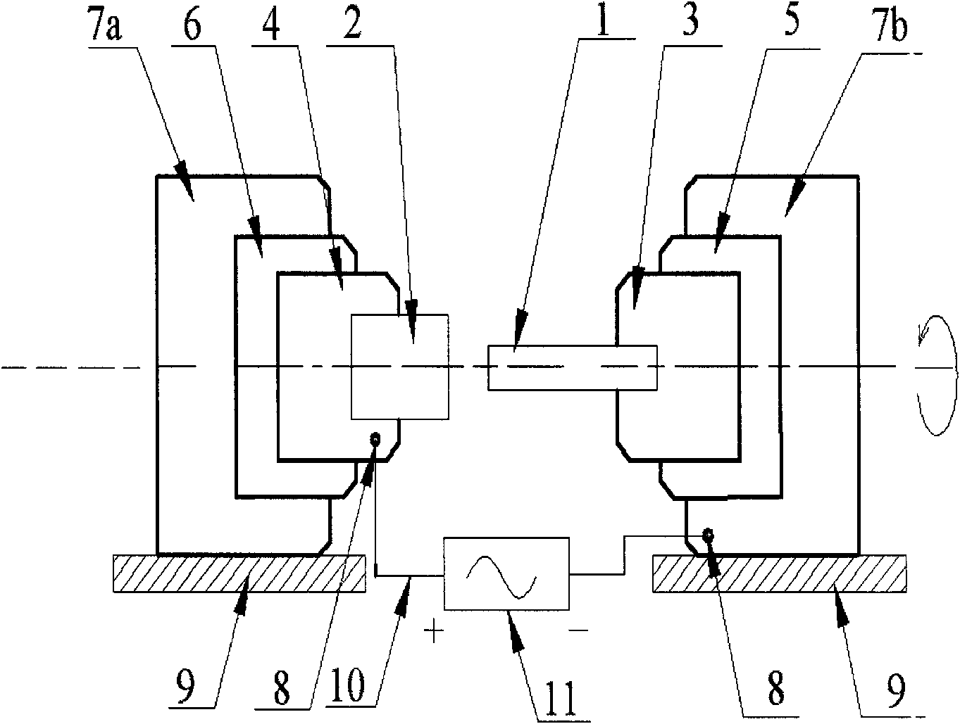
[0040] The welding dissimilar materials are T3 copper ring and 35CrMnSi steel rod, the inner diameter of the copper ring and the outer diameter of 35CrMnSi steel are both 30mm, the thickness of the copper ring is 4mm, the width of the copper ring is 5mm, the length of the 35CrMnSi steel rod is 150mm, and the current-carrying inertia radial The friction composite welding method and its equipment are used for welding. The friction spindle speed is 4200rpm, the friction pressure is 60Mpa, the upsetting pressure is 200Mpa, and the digital inverter arc welding power supply is used as the external power supply. The external current provided is 320A, and the performance is good. welded joints.

Embodiment 2

[0042] The welding dissimilar materials are Q235 steel ring and 45CrMo steel rod, the inner diameter of Q235 steel ring and the outer diameter of 45CrMo steel are both 30mm, the thickness of Q235 steel ring is 3mm, the width of Q235 steel ring is 4mm, and the length of 45CrMo steel barrier is 200mm. The inertial drive radial friction composite welding method and its equipment are used for welding. The friction spindle speed is 5400r / min, the friction pressure is 70Mpa, and the upsetting pressure is 230Mpa. The digital inverter resistance welding power supply is used as the external power supply, and the external current is 500A. , the current frequency is 50Hz, and the duty cycle is 80%, and a welded joint with good performance is obtained.


PUM


Abstract

The invention relates to a current-carrying inertial radial friction composite welding method and equipment thereof. In the inertial radial friction welding process, a unique current loading method without an electric brush is adopted, current is introduced into a friction welding head to enable a friction interface to generate resistance heat, and the resistance heat and friction heat form a friction composite heat source for together heating joints and carrying out friction and plastic deformation to realize the purpose of welding through the method and the equipment. The method and the equipment can shorten the heating time of friction welding, improve the production efficiency of welding, reduce the friction pressure, the power of a main shaft and the special requirements for the capacity of a friction welding machine, can adopt resistance heat to carry out heat treatment after welding and preheating before welding on welding seams and improve the structure property of joints, and are especially suitable for friction welding of rotator joints of high-melting point and high-hardness dissimilar materials, small-size or oversize rings or bars and the like.

Description

technical field [0001] The invention belongs to the field of welding technology, and relates to a current-carrying inertial radial friction composite welding method and equipment thereof, relates to a current loading mode of current-carrying inertial radial friction welding, and also relates to a current loading device of current-carrying inertial radial friction welding. Background technique [0002] Radial friction welding is a typical solid-phase welding method. Its welding process principle is as follows: After assembling the two workpieces to be welded in the specified position, the hydraulic system of the welding machine pushes the conical mold, and the axial The pressure is transformed into radial pressure, which causes the two workpieces to be welded to rub against each other, generating frictional heat at the interface, heating the joint and producing plastic deformation, and finally, under the action of the upsetting force, the radial friction welding process of the...

Claims


Application Information

Patent Timeline
IPC IPC(8): B23K28/02B23K20/12B23K11/00
Inventor 罗键
Owner CHONGQING UNIV
Why Eureka
Try Eureka