
Disk knitter gear structure

A gear structure, knitting machine technology, applied in belts/chains/gears, mechanical equipment, components with teeth, etc., can solve the problems of heavy tooth body, inconvenient replacement and assembly, loud pinion meshing noise, and low service life. , to achieve the effect of low noise, short processing cycle and low cost

Inactive Publication Date: 2010-09-15
福建台帆实业有限公司
View PDF0 Cites 2 Cited by
  • Summary
  • Abstract
  • Description
  • Claims
  • Application Information

AI Technical Summary

Problems solved by technology

[0005] In general, the disadvantages of the steel gear on the upper plate: the sound of meshing with the small gear on the side is loud when rotating, the production process is complicated, the processing cycle is long and the cost is high, the tooth body is heavy and it is inconvenient to replace and assemble, and the service life is not long

Method used


Image

  • Disk knitter gear structure
  • Disk knitter gear structure
  • Disk knitter gear structure

Examples


Embodiment

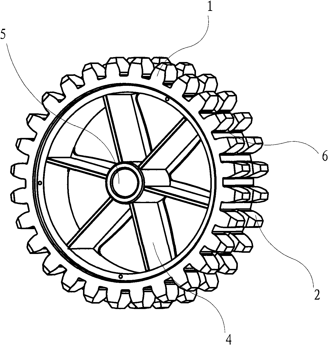
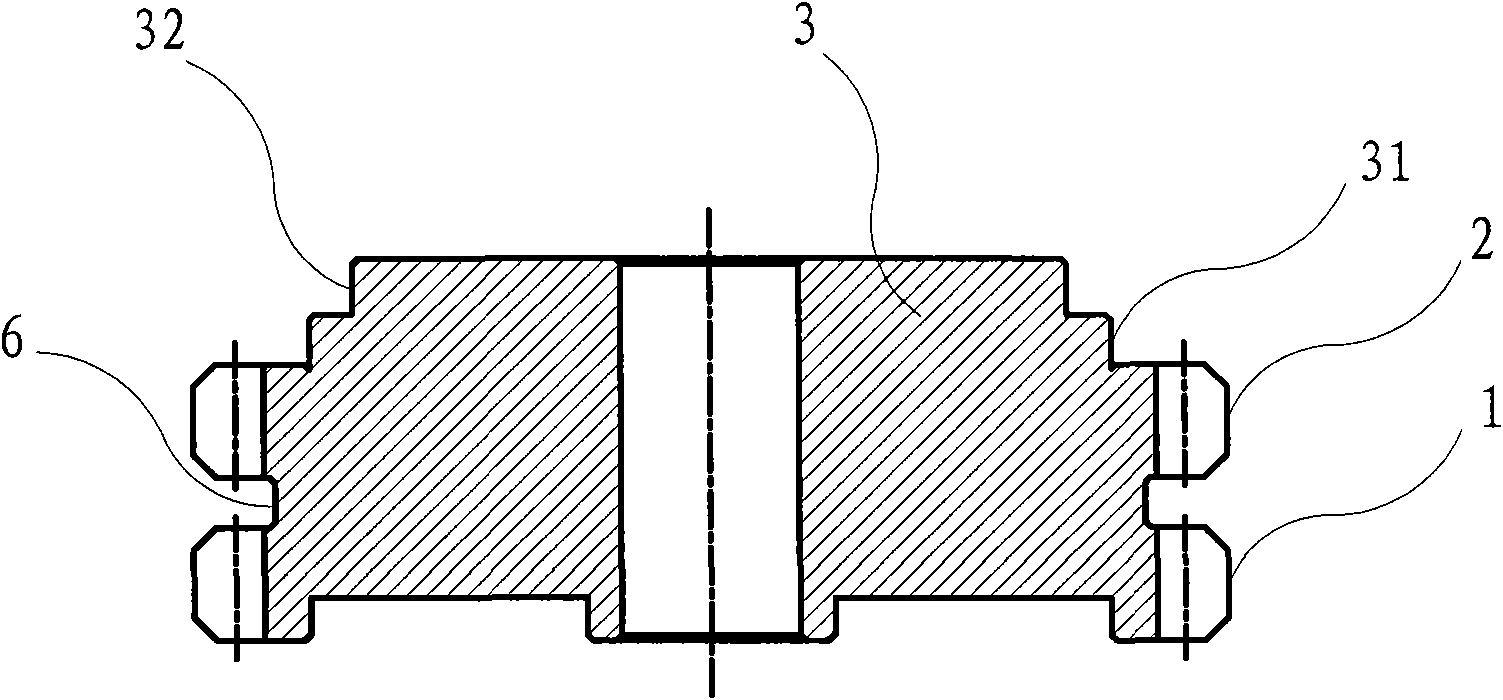
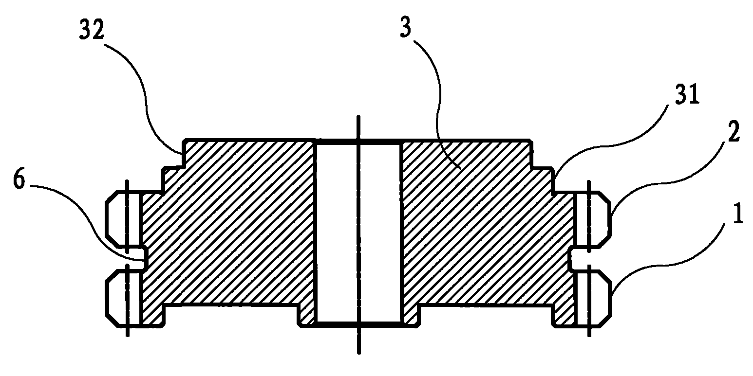
[0033] Example: see figure 1 , a disc knitting machine gear structure, which is an integrated structure processed by nylon material, the gear includes a spoke 4, an external gear ring and a boss ring (body) 3 for assembly, wherein the spoke 4 The peripheral side of the outer gear ring and the boss ring 3, the boss ring 3 is arranged on one side of the outer gear ring, the outer gear ring is composed of the upper and lower gear rings 1, 2 combined into one, the upper and lower gear rings 1 and 2 are separated by an annular groove 6, and the toggle teeth of the upper and lower ring gears 1 and 2 are the same, and each toggle tooth of the above two ring gears extends to the inner and outer ends of the top surface of the ring gear along the gear axis. The above-mentioned boss ring 3 is composed of two cylindrical rings 31 and 32 with different diameters, and the diameter of the outer cylindrical ring 32 is smaller than the diameter of the middle cylindrical ring 31, the diameter o...


PUM

PropertyMeasurementUnit
widthaaaaaaaaaa
widthaaaaaaaaaa

Abstract

The invention discloses a disk knitter gear structure which is an integrated structure processed by nylon materials. The gear comprises a spoke, an outer gear ring and a lug loop for assembling, wherein the outer gear ring and the lug loop are arranged at the circumferential side of the spoke; the lug loop is arranged at one side of the outer gear ring; the outer gear ring is combined by an upper gear ring and a lower gear ring; the upper gear ring and the lower gear ring are separated by an annular groove; the shifting teeth of the upper gear ring and the lower gear ring are identical; and each shifting tooth of the two gear rings extends to the inner end and the outer end of the top surface of each gear ring along the axial direction of the gear. The disk knitter gear of the invention is processed and formed by nylon materials; because nylon is one of plastic materials, when the disk knitter gear is meshed with peripheral small gears, the meshing process has low noise and nearly has no noise; and the disk knitter gear has the advantages of strong wear resistance, noise absorption, shock reduction, convenient maintenance, low production cost and the like.

Description

technical field [0001] The invention discloses a gear structure of a circular knitting machine, belongs to the technical field of loom gear manufacturing according to the International Patent Classification (IPC), and particularly relates to an upper plate gear applied to a circular knitting machine. Background technique [0002] Disc knitting machine is a kind of loom commonly used in the knitting industry. The loom parts on the market are generally welded or cast by metal. Since the related parts of the loom are easy to wear components, they are not easy to disassemble and repair once damaged. [0003] The upper plate gear of the disc loom is driven by the drive shaft and pinion gear arranged on its side, and then the drive shaft drives the upper plate of the loom to rotate, so that the needle cylinder rotates relative to the cam mechanism to realize the knitting function. The existing upper plate gear is made of ordinary cast iron or steel, and the radial contact surface ...

Claims


Application Information

Patent Timeline
Patent Type & Authority Applications(China)
IPC IPC(8): F16H55/06F16H55/17B29C41/04B29C41/52B29K77/00
Inventor 许文谈柯清稿
Owner 福建台帆实业有限公司
Learn More