
High compressed air cylinder filling machine

A high-compression and compression cylinder technology, applied in liquid variable volume machinery, gas/liquid distribution and storage, mechanical equipment, etc., can solve problems such as easy use that is not suitable for general consumers

Active Publication Date: 2010-09-22
昌祺国际有限公司
View PDF5 Cites 5 Cited by
  • Summary
  • Abstract
  • Description
  • Claims
  • Application Information

AI Technical Summary

Problems solved by technology

[0006] The above-mentioned Chinese patent authorization announcement number is No. CN2761870Y patent case, which involves the use of multiple compression cylinders of different sizes to compress natural gas. The compression structure is not suitable for general consumers or for easy use in various professional fields; therefore, compared with the performance of a high-compression gas bottle filling machine of the present invention, the mentioned Chinese Patent No. CN2761870Y should not be regarded as products that are demanded by the average consumer of the same class

Method used


Image

  • High compressed air cylinder filling machine
  • High compressed air cylinder filling machine
  • High compressed air cylinder filling machine

Examples


Embodiment Construction

[0021] The principle and structure of the present invention are now further described in detail as implementation examples in conjunction with the accompanying drawings; however, the implementation examples are only for providing illustration and explanation, and should not be used to limit the practical extension scope of the present invention and its invention claims scope of protection.

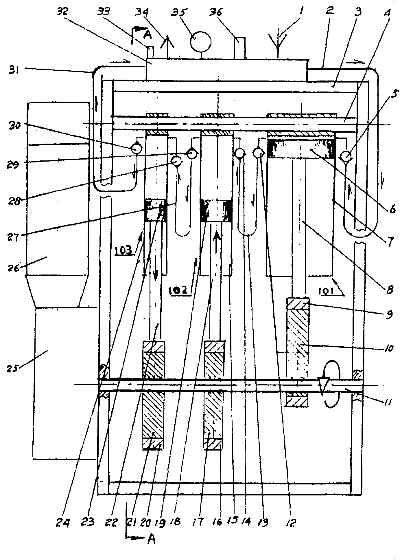
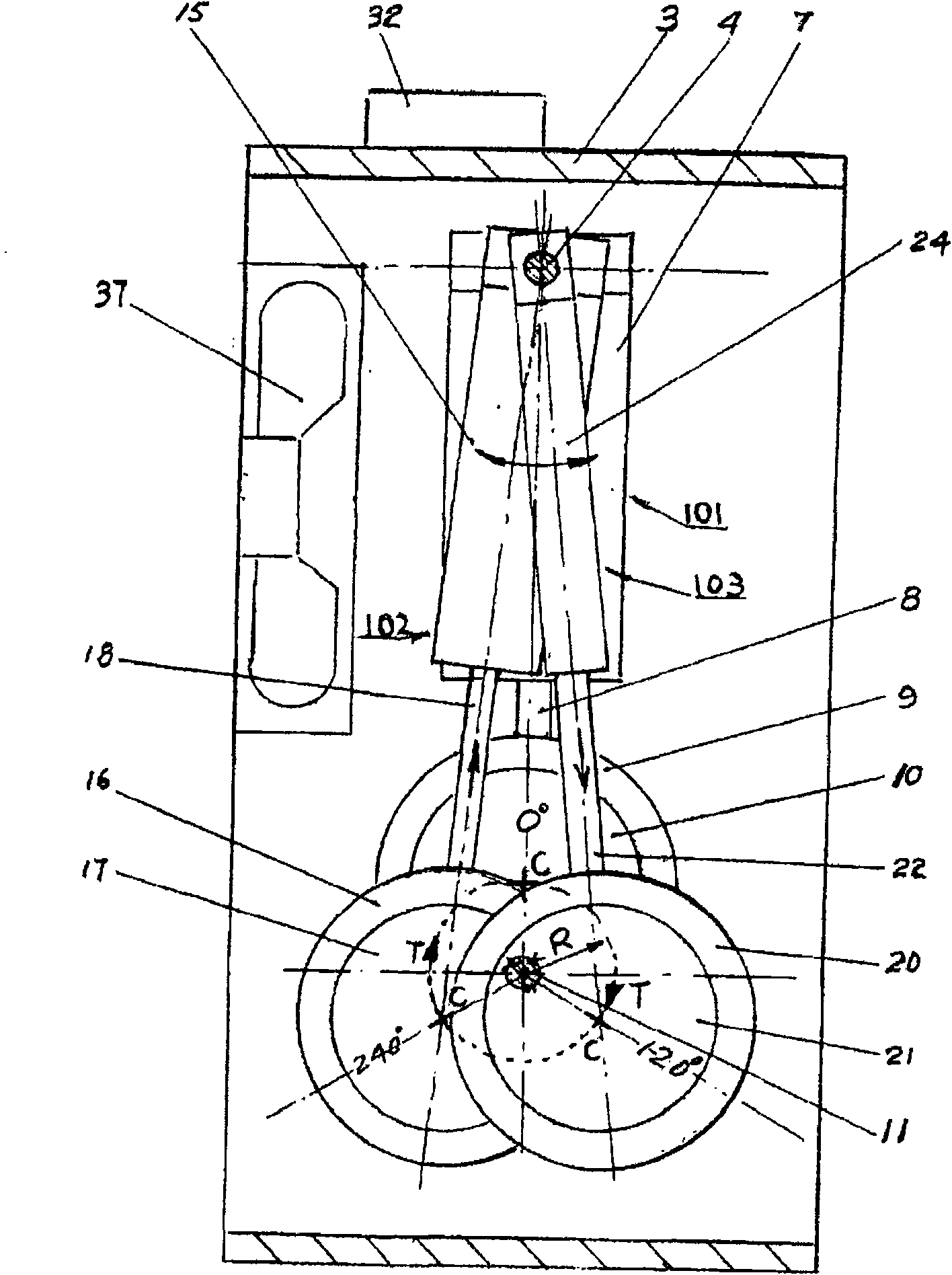
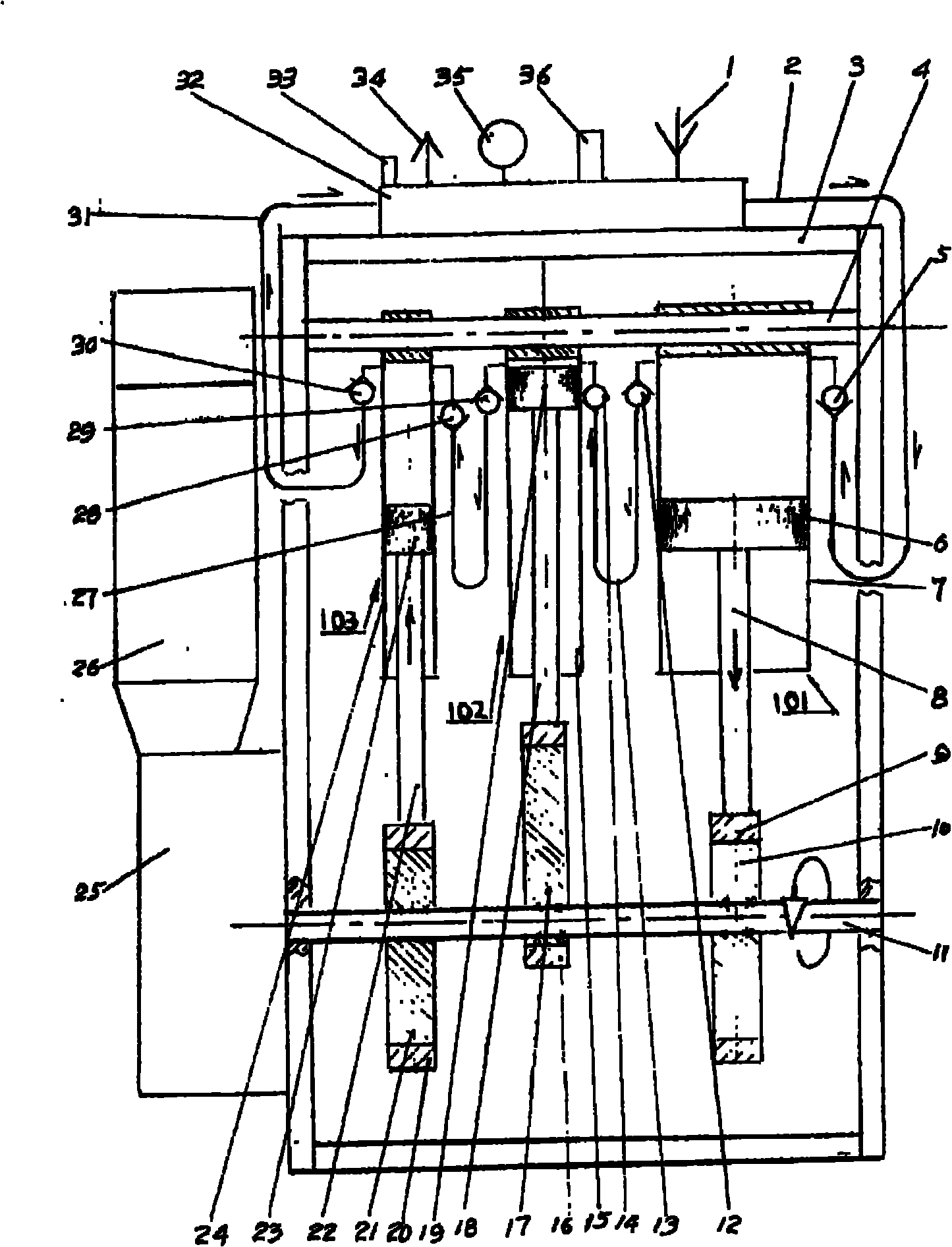
[0022] Such as Figure 1 to Figure 4 Demonstration: According to the preferred implementation example of the high-compression gas bottle filling machine 100 of the present invention, the operating organization of the present invention mainly includes an eccentric drive mechanism and a group of pendulum compression cylinder mechanisms; Box 25, drive shaft 11, and three eccentric drive wheels 10, 17, 21 are formed, and according to the preferred implementation example of the present invention, described one group of pendulum type compression cylinder mechanism is to select three pendulum typ...


PUM


Abstract

The invention relates to a high compressed air cylinder filling machine comprising an electric driving machine, a reduction gearbox and a drive shaft. An eccentric driving mechanism comprising at least two eccentric driving wheels is mounted on the drive shaft; at least two swing type compression cylinders are connected in series with a plurality of one-way valves and hose pipes to form a high compression mechanism, and are connected with a piston, a piston rod and a slide ring to be as a whole and then sleeved on the eccentric driving wheels through the slide ring; the other end of the piston rod is connected with a cylinder barrel which is sleeved on a supporting shaft which is mounted in a frame-shaped stand; a confluence plate is mounted on the frame-shaped stand and is provided with a pressure switch, a pressure gauge and a safety valve; the outer circumference of the compression cylinder is provided with concave-convex lines for heat dispersion; the frame-shaped stand is internally provided with a cooling fan, and the frame-shaped stander is provided with a transparent outer cover; the electric driving machine drives the reduction gearbox to transmit rotating motion to the drive shaft so as to enable the eccentric driving wheels to rotate and subsequently to drive the slide ring, the piston rod and the piston entirely to make straight reciprocating motion relative to the cylinder barrel for compressing gas, and the gas compressed by multistage is output to fill in a high pressure storage cylinder.

Description

technical field [0001] The invention mainly relates to a high-compression gas bottle filling machine, which is specially used for highly compressing gas and then filling it into high-pressure gas storage cylinders for use by general consumers or various professional fields, and can be made of composite materials in the market. The need for large capacity of ultra-high pressure gas storage cylinders. Background technique [0002] A high-compression gas bottle filling machine provided by the present invention, its compression technical operation is mainly produced by the cooperation of a group of high-compression mechanisms and a group of eccentric drive mechanisms; the group of high-compression mechanisms used in the present invention includes at least Two or more pendulum compression cylinders of different sizes, and a group of eccentric drive mechanisms including at least two or more eccentric drive wheels are fixedly installed on the drive shaft at an angle of 120 degrees ...

Claims


Application Information

Patent Timeline
Patent Type & Authority Applications(China)
IPC IPC(8): F17C5/06F17C13/00F17C13/02
CPCF04B27/0404F04B27/0414F04B25/00F04B35/04Y10T74/2101Y10T137/9247Y10T137/86002
Inventor 郑镇邦谭炳文
Owner 昌祺国际有限公司
Learn More