Solar linear multi-mirror zooming and unidirectional tracking system and application

A tracking system and solar mirror technology, applied in the field of solar energy utilization, can solve the problems of inability to guarantee thermal insulation requirements, inability to achieve tracking, and failure to solve the focal line, etc., to reduce heat loss in collection and transmission, high-efficiency heat collection and transmission, and reduce The effect of range of motion

Inactive Publication Date: 2010-09-22
BEIJING WISWORD HI TECH
View PDF1 Cites 2 Cited by
  • Summary
  • Abstract
  • Description
  • Claims
  • Application Information

AI Technical Summary

Problems solved by technology

In the process of tracking solar energy, the heat transfer oil moves together in the pipe, and the bellows are used at the heat transfer oil pipe and the outflow end to realize the connection between the moving pipe and the non-moving pipe; because the bellows need high temperature resistance and high reliability, etc. Requirements, so it becomes a key component, and at the same time, this kind of connection cannot guarantee the thermal insulation requirements, so the heat loss of the system is very high
[0004] Chinese patent 200710176966 provides a combined tracking system, which can be used in a trough-type and tower-type combined tracking system. The tracking method adopts the method of keeping the focus fixed while the solar mirror system moves. It is mainly set on the ground. Two orbits are used for tracking, and the line-focusing system of the trough system uses its linear axis to be placed parallel to the earth's self-propagation axis, so it can use rotation in one direction to achieve tracking, but this scheme uses rotation on the ground to achieve trough tracking. Obviously, tracking cannot be realized, so the inventor further set pitch tracking in the scheme, so that the trough system is not one-way tracking, but two-way tracking, so the inventor did not solve the problem that the focal line does not move when the trough one-way tracking question
[0005] The inventor announced the solar energy utilization system of zoom tracking in the invention of 200610020352, which mainly adopts disc or cross bidirectional tracking to realize zoom tracking, but this system does not adopt unidirectional tracking

Method used


Image

  • Solar linear multi-mirror zooming and unidirectional tracking system and application
  • Solar linear multi-mirror zooming and unidirectional tracking system and application
  • Solar linear multi-mirror zooming and unidirectional tracking system and application

Examples


Embodiment 1

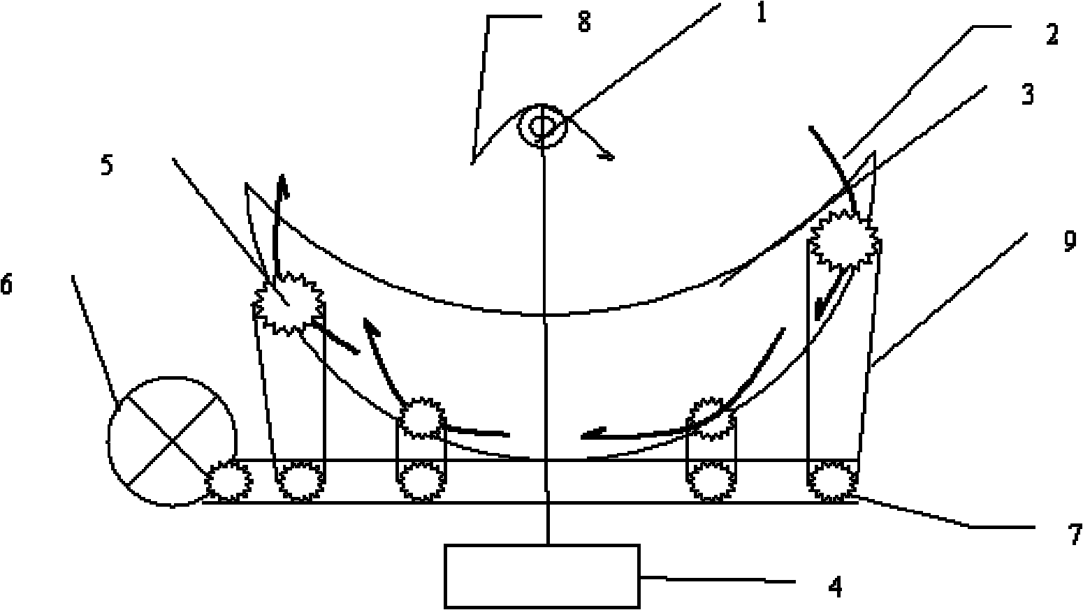
[0064] Embodiment 1: Multi-parabolic mirror solar line tracking and utilization system

[0065] This figure is a side view, the solar mirror (2) is four parabolic reflectors (2), the solar energy utilization device (1) is a heat pipe, and the parabolic mirror is arranged on a parabolic device, and each parabolic mirror is set There is an axis, and the solar mirror can rotate along the rotating shaft (5). The four solar mirrors track the solar energy through different movements, and at the same time focus the solar light on the heat pipe (10). The four parabolic mirrors use the same drive In the system, the transmission mechanism is a gear set, and different solar mirrors have different gear teeth numbers, so that different solar mirrors can be driven to move at different speeds, so as to realize tracking and utilization of solar energy.

Embodiment 2

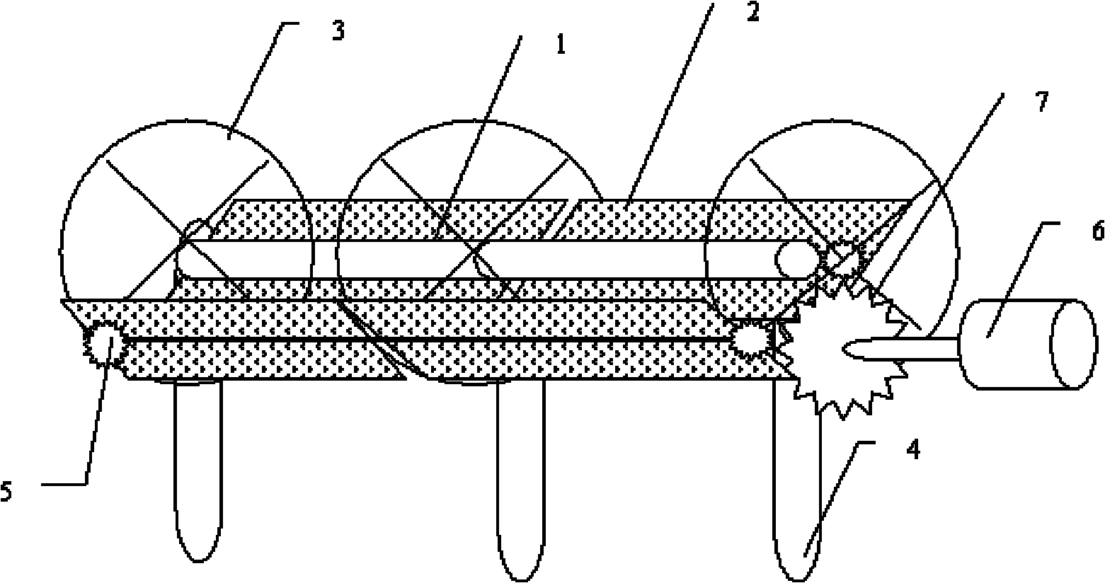
[0066] Embodiment 2: Dofresnel mirror tracking and utilization system

[0067] Such as figure 2 As shown, this example uses a double-group Fresnel reflector system to realize solar tracking, wherein each set of solar mirrors is 2 Fresnel reflectors, and the two sets of solar mirror tracking systems are connected in series; the solar energy utilization device (1) is a solar Photovoltaic and photothermal comprehensive utilization system, the monocrystalline silicon solar panel is installed inside the vacuum tube, and a water cooling device is also installed to provide heat dissipation for the solar panel, so that both focused photovoltaic power generation and hot water utilization can be realized ; Four Fresnel reflectors are fixed on three ring-shaped devices, the power drive device is a motor (6), the power transmission device is a gear mechanism arranged on the ring, and the motor is driven by the gear mechanism to be arranged on the ring The gear on the top makes the solar...

Embodiment 3

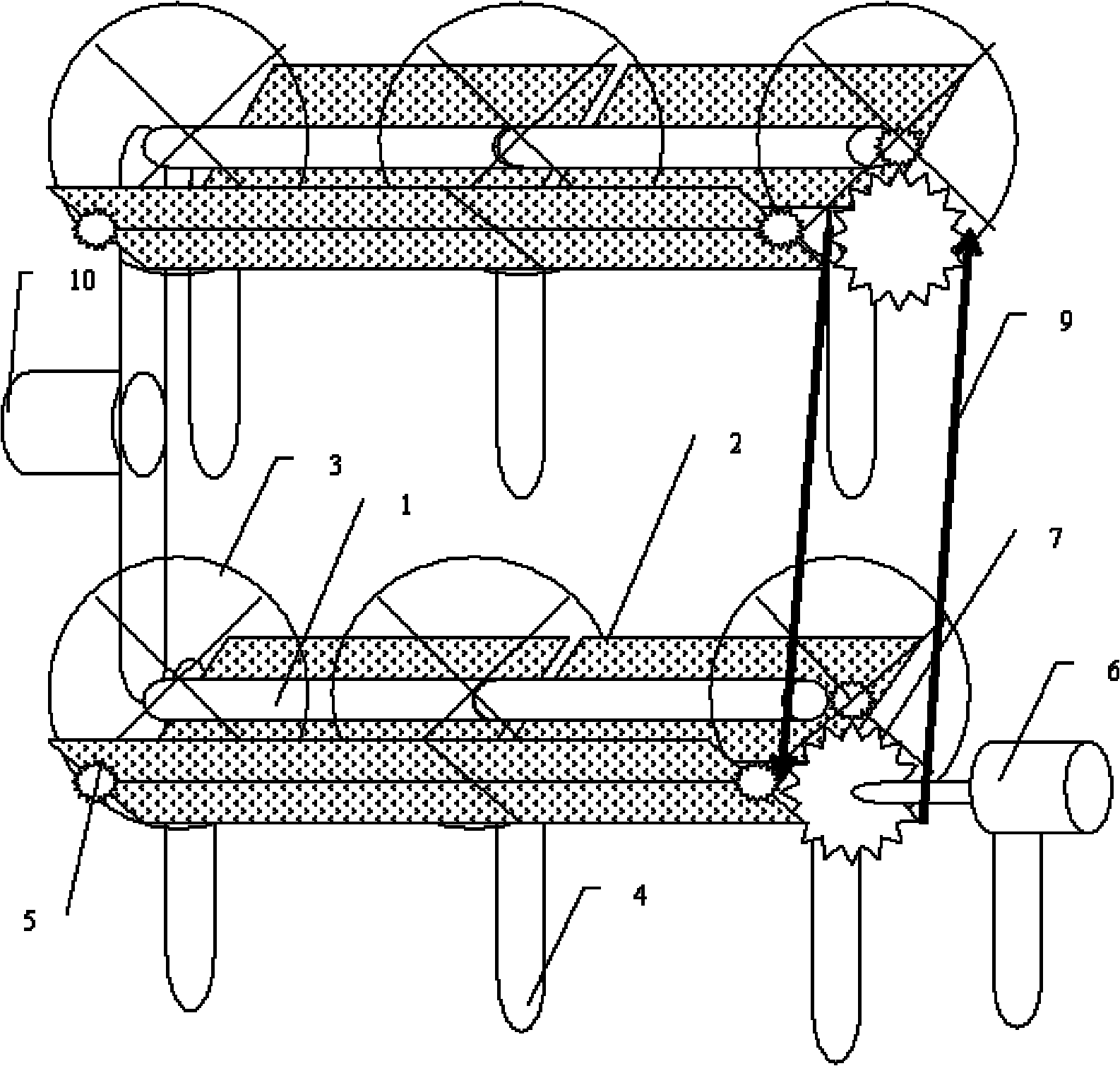
[0068] Embodiment 3: Dofresnel mirror tracking array tracking and utilization system

[0069] Such as Figure three As shown, this case is a multi-mirror array tracking system, using four Fresnel mirrors, the power drive device is a motor, and the motor drives two gears set on the focal line shaft through the power transmission equipment of the chain to realize the alignment of 2 *2 Array solar tracking, the solar energy utilization equipment is a heat pipe system, the heat pipe is the evaporation end of the heat pipe formed by the focal line part of the two sets of reflectors, the two evaporation ends are connected together to form the condensation end, and the condensation end exchanges heat with it Heat exchange with the device to form high-temperature and high-pressure steam, thereby realizing solar thermal power generation.


PUM


Abstract

The invention discloses a solar linear multi-mirror zooming and unidirectional tracking system and application. In the system, a group of solar optical mirrors consisting of a plurality of reflecting mirrors, a Fresnel mirror, and a plane mirror are adopted; a resolving shaft of each mirror is arranged on a non-linear device; each solar optical mirror can rotate around the shaft; as solar energy utilization equipment is arranged in a cylinder interval on ground or a building, when the solar mirror moves, the solar energy utilization equipment keeps still, and the focal length is variable zooming and tracking; and the solar energy utilization equipment is arranged in a cylinder, so that the utilization of the focused and tracked solar energy is realized. The invention provides an array structure of the system, which is suitable for systems of different scales, and simultaneously suitable for large-scale unitization of the solar energy, particularly photovoltaic generation, thermal power generation, high-temperature steaming, heating and cooking of the solar energy.

Description

technical field [0001] The invention relates to the utilization of solar energy, in particular to the linear tracking in which the focusing and tracking focus of solar energy is a straight line, as well as the array tracking and utilization thereof. Background technique [0002] Solar tracking mainly consists of three types: trough type, tower type and butterfly type. Because the trough type system is one-way tracking, the relative technical difficulty is relatively low. At the same time, due to the solar energy selective coating and vacuum tube technology, it has industrial production in the temperature range of 100-400 degrees. Therefore, it can be mass-produced quickly, and the earliest commercial application in the world is the trough system. [0003] The main tracking method of the trough system in the world is to set a heat exchange tube at the focal line position of the trough system, fill the heat exchange tube with heat transfer oil, and the motor drives the flow of...

Claims


Application Information

Patent Timeline
Patent Type & Authority Applications(China)
IPC IPC(8): F24J2/38F24J2/46F24J2/52G05D3/20F24S50/20
CPCY02E10/47
Inventor 李建民
Owner BEIJING WISWORD HI TECH
Why Eureka
Try Eureka