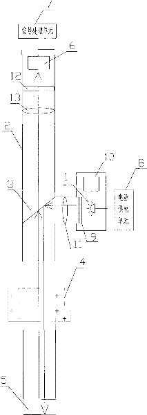
Device for testing residence time distribution (RTD) of material
A residence time and distribution testing technology, applied in measuring devices, material excitation analysis, material analysis through optical means, etc., can solve problems such as melting of adhesives, inconvenient use, fiber detachment, etc., to reduce coupling loss and cost, Compact optical path layout, convenient isolation effect
- Summary
- Abstract
- Description
- Claims
- Application Information
AI Technical Summary
Problems solved by technology
Method used
Image
Examples
Embodiment 1
[0022] like figure 1 As shown, the material residence time distribution test device includes an excitation light source 1, a light tube 2, a half mirror 3, a heat insulation layer 4, an optical window 5, a fluorescence detector 6, a signal processing unit 7, a power supply unit 8, Excitation light source filter 9 , light source lens 11 , fluorescence filter 12 and fluorescence lens 13 . The excitation light source 1 described in this embodiment is a light-emitting diode, and the light-transmitting cylinder 2 is a stainless steel cylinder that is opaque and resistant to high temperature. The power supply unit 8 is a constant current power supply, which provides driving for the light-emitting diodes, so that the light-emitting diodes emit stable excitation light beams. A light source detector 10 is provided at the excitation light source 1 to monitor the stability of the excitation light source 1 and compensate the measurement results according to the fluctuation of the excitat...
Embodiment 2
[0025] like figure 2 As shown, the material residence time distribution test device includes an excitation light source 1, a light tube 2, a half mirror 3, a heat insulation layer 4, an optical window 5, a fluorescence detector 6, a signal processing unit 7, a power supply unit 8, Light source lens 11 and fluorescent lens 13. The excitation light source 1 described in this embodiment is a light-emitting diode, and the light-transmitting cylinder 2 is a stainless steel cylinder that is opaque and resistant to high temperature. The power supply unit 8 is a constant current power supply, which provides driving for the light-emitting diodes, so that the light-emitting diodes emit stable excitation light beams. The excitation light beam passes through the light tube 2, passes through the light source lens 11, the half-mirror 3 and the optical window 5 in sequence to reach the material to be measured. The tracer in the material to be tested emits fluorescence of a certain band af...
Embodiment 3
[0028] like image 3As shown, the material residence time distribution test device includes an excitation light source 1, a light tube 2, a half mirror 3, a heat insulation layer 4, an optical window 5, a fluorescence detector 6, a signal processing unit 7, a power supply unit 8, Excitation light source filter 9 , light source lens 11 , fluorescence filter 12 and fluorescence lens 13 . The excitation light source 1 described in this embodiment is a light-emitting diode, and the light-transmitting cylinder 2 is a stainless steel cylinder that is opaque and resistant to high temperature. The power supply unit 8 is a constant current power supply, which provides driving for the light-emitting diodes, so that the light-emitting diodes emit stable excitation light beams. A light source detector 10 is provided at the excitation light source 1 to monitor the stability of the excitation light source 1 and compensate the measurement results according to the fluctuation of the excitati...
PUM
 Abstract
Description
Claims
Application Information
 - R&D
- Intellectual Property
- Life Sciences
- Materials
- Tech Scout
- Unparalleled Data Quality
- Higher Quality Content
- 60% Fewer Hallucinations
Browse by: Latest US Patents, China's latest patents, Technical Efficacy Thesaurus, Application Domain, Technology Topic, Popular Technical Reports.
© 2025 PatSnap. All rights reserved.Legal|Privacy policy|Modern Slavery Act Transparency Statement|Sitemap|About US| Contact US: help@patsnap.com


