Subnanosecond high-voltage pulse measurement system

A measurement system, high-voltage pulse technology, applied in the direction of measuring devices, measuring electrical variables, measuring current/voltage, etc., can solve the problem of inability to meet high-voltage pulse accurate measurement, limited application range of capacitive voltage divider, complex structure of capacitive voltage divider, etc. Problems, to achieve the effect of compact structure, simple installation and easy operation

Active Publication Date: 2010-09-22
REMEDICINE CO LTD
View PDF5 Cites 13 Cited by
  • Summary
  • Abstract
  • Description
  • Claims
  • Application Information

AI Technical Summary

Problems solved by technology

The main disadvantages of this capacitive voltage divider are: when measuring, it is necessary to pour epoxy resin around the wire, implant electrode wrapping, install a voltage divider box, etc. The structure of this capacitive voltage divider is complex, inconvenient to operate, and the cost is high; change The medium around the wire that transmits the nanosecond high-voltage pulse signal has a great impact on the source signal and affects the accuracy of the measurement; the introduction of wiring inductance reduces the bandwidth of the measurement. The application range of the capacitive voltage divider is limited and cannot meet The need for accurate measurement of sub-nanosecond or even narrower high-voltage pulses

Method used


Image

  • Subnanosecond high-voltage pulse measurement system
  • Subnanosecond high-voltage pulse measurement system
  • Subnanosecond high-voltage pulse measurement system

Examples


Embodiment 1

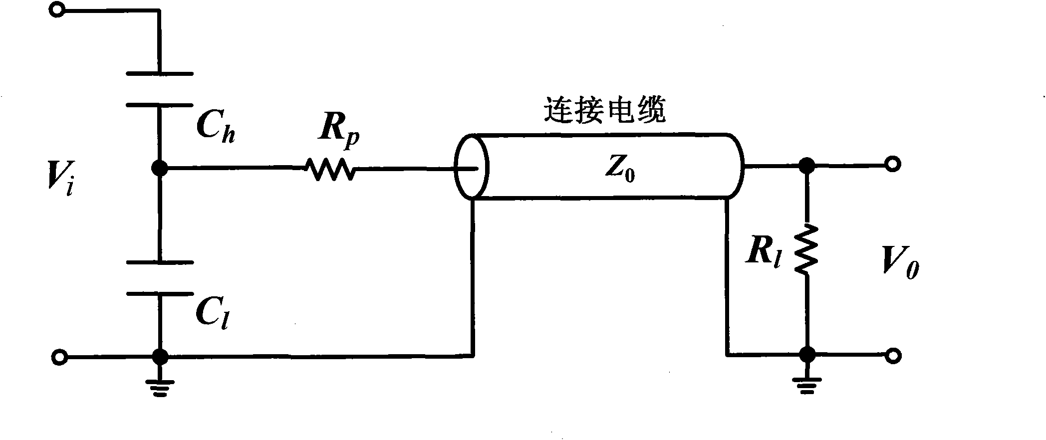
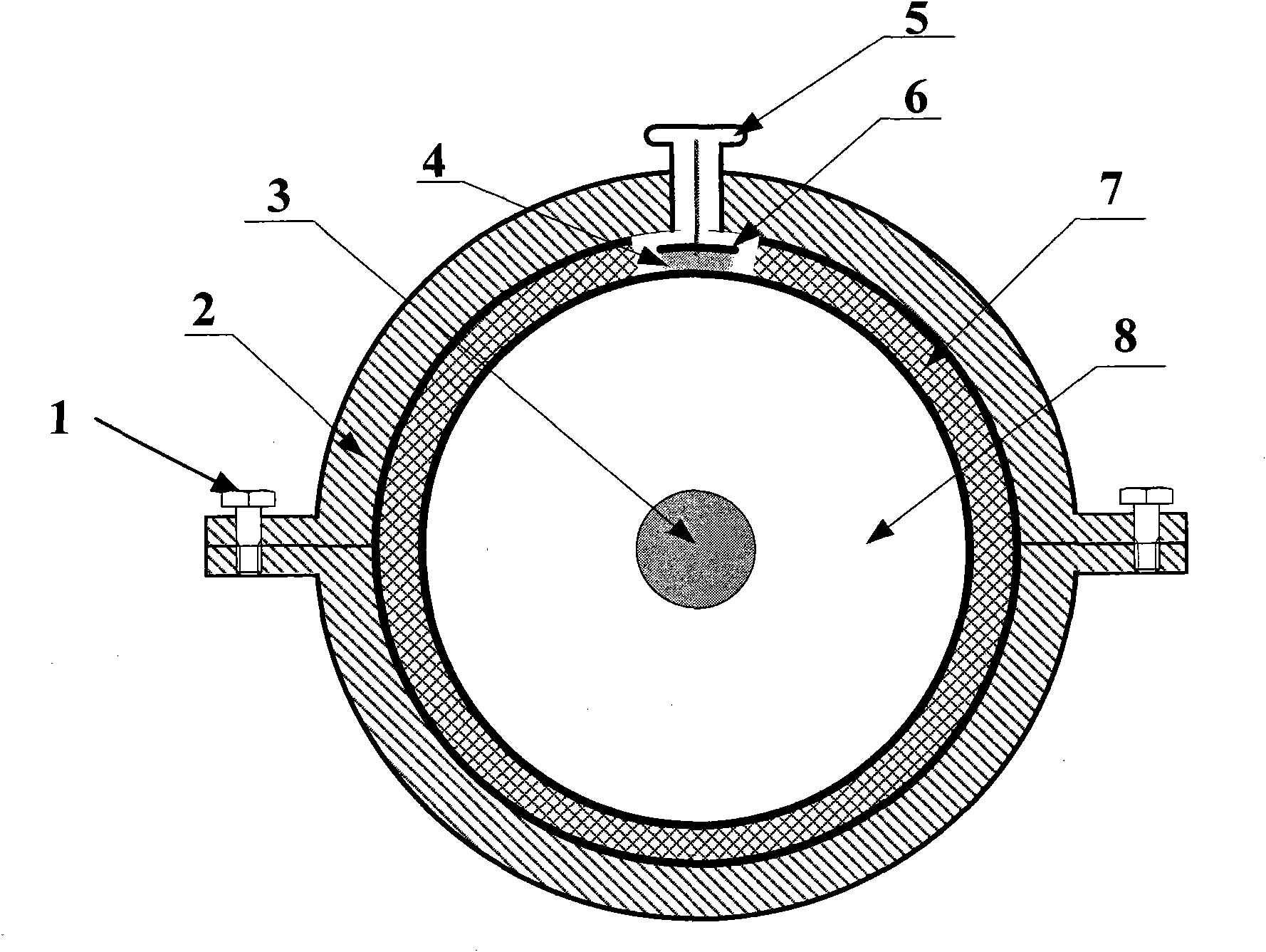
[0021] Such as Figure 1~2 As shown, a sub-nanosecond high-voltage pulse measurement system mainly includes a coaxial capacitive voltage divider, a non-inductive resistor Rp, and an oscilloscope.

[0022] The coaxial capacitive voltage divider (hereinafter referred to as the voltage divider) is mainly composed of a copper sheet 4, a polyethylene insulating film sheet 6, an SMA interface 5, and a U-shaped clip 2. One side of the copper sheet 4 is closely pasted on the outer surface of the insulating layer 8 of the peeled sheath and the ground grid 7 in a small slit of the coaxial cable, and the other side of the copper sheet 4 is closely pasted with a polyethylene insulating film sheet 6 . The commercially available SMA interface 5 (similar to the terminal block interface, because of the high bandwidth of the sub-nanosecond pulse signal, the SMA interface 5 is required to accurately lead out the sub-nanosecond pulse signal without loss) is mainly composed of a central core wire...

Embodiment 2

[0026] A sub-nanosecond high-voltage pulse measurement system is the same as in Embodiment 1, wherein: the resistance value of the non-inductive resistor Rp is 50kΩ.

Embodiment 3

[0028] A sub-nanosecond high-voltage pulse measurement system is the same as that in Embodiment 1, wherein: the resistance value of the non-inductive resistor Rp is 100 kΩ.


PUM


Abstract

The invention discloses a subnanosecond high-voltage pulse measurement system and relates to a device for measuring subnanosecond high-voltage pulse signals transmitted in a coaxial cable. The measurement system mainly comprises a coaxial capacitive voltage divider, a noninductive resistor, and an oscilloscope. The coaxial capacitive voltage divider in the device effectively uses stray parameters between inner and outer conductors of the structure and the coaxial cable. By adopting the crimping mode to connect the components, the lead-in inductance is effectively reduced, and the system measurement bandwidth is improved. The subnanosecond high-voltage pulse measurement system have the advantages of simple structure, convenient installation, no change of the signal transmission medium structure in the coaxial cable, and no influence on the originally transmitted signals, and can be widely applied to the measurement of high-voltage pulse signals in the coaxial cable.

Description

technical field [0001] The invention belongs to the technical field of sub-nanosecond high-voltage pulse measurement, and in particular relates to a measuring device for measuring sub-nanosecond high-voltage pulse signals transmitted in coaxial cables. Background technique [0002] Using an oscilloscope to directly measure low-voltage pulse signals is a very convenient engineering technique. However, for high-voltage pulse signals, it cannot be directly observed with an oscilloscope. Sub-nanosecond high-voltage pulse signals are often used as transmission media with coaxial cables. Therefore, accurate measurement of sub-nanosecond high-voltage pulse signals transmitted in coaxial cables can provide reliable and accurate sub-nanosecond measurements for communications, radar, and medical industries. Pulse signal source is the focus and hot spot of engineering technology research. [0003] Existing measuring devices for high-voltage pulse signals, such as the patent applicatio...

Claims


Application Information

Patent Timeline
Patent Type & Authority Applications(China)
IPC IPC(8): G01R19/00G01R15/06
Inventor 姚陈果赵东阳唐炬李成祥张晓星米彦孙才新
Owner REMEDICINE CO LTD
Why Eureka
Try Eureka