Novel cervical vertebra dynamic internal fixing device

A fixation device and cervical spine technology, applied in the direction of internal fixator, fixator, internal bone synthesis, etc., can solve the problems of inability to achieve dynamic fixation of cervical spine, accelerated degeneration of adjacent segmental intervertebral discs, etc., and achieve physiological mobility and stability stability, retention of stability and activity, and broad application prospects

Active Publication Date: 2010-09-29
东人
View PDF6 Cites 11 Cited by
  • Summary
  • Abstract
  • Description
  • Claims
  • Application Information

AI Technical Summary

Problems solved by technology

[0003] Up to now, at home and abroad, patients with cervical disc degenerative diseases who undergo single anterior cervical subtotal corpectomy need one-stage bone graft fusion. This type of surgery has been proved to be safe and effective in providing good stability of the cervical spine , but at the expense of the physiological function of the cervical spine at the fusion segment, and may cause accelerated degeneration of the adjacent segmental intervertebral disc
[0004] Although the existing cervical artificial intervertebral discs on the market can achieve some physiological activities of the cervical spine to a certain extent, due to the limitations of the surgical method and the structural design of the artificial intervertebral disc itself, it is still impossible to achieve cervical vertebrae after subtotal corpectomy. Dynamic fixation of

Method used


Image

  • Novel cervical vertebra dynamic internal fixing device
  • Novel cervical vertebra dynamic internal fixing device
  • Novel cervical vertebra dynamic internal fixing device

Examples


Embodiment Construction

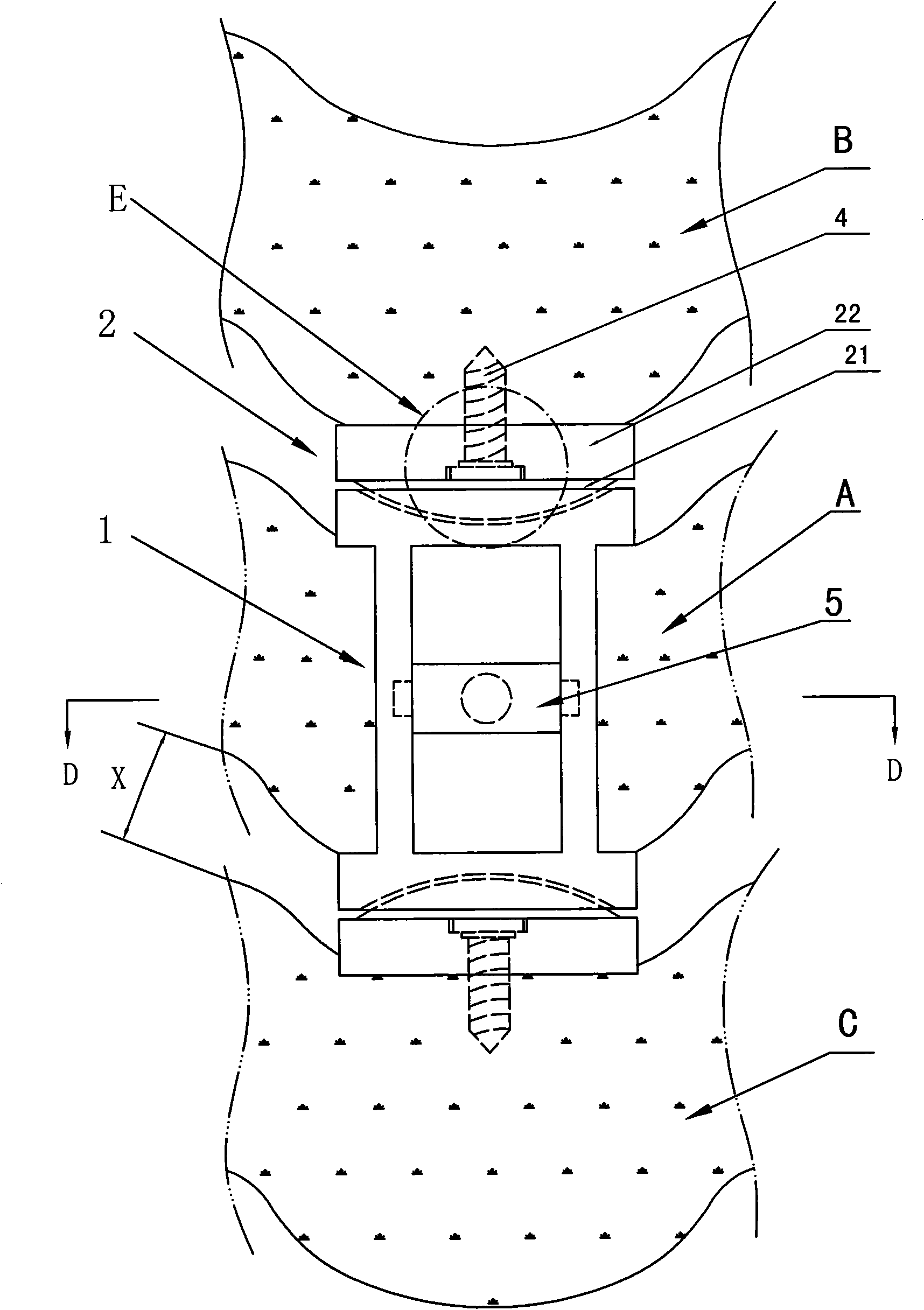
[0053] see figure 1 , 20 , with reference to Figure 2-19 , a cervical dynamic internal fixation device related to the present invention, mainly comprising a cervical artificial vertebral body 1 and an artificial intervertebral disc 2;

[0054] Such as figure 1 , 13, 20, the cervical artificial vertebral body 1 is embedded on the vertebral body A of any one of the 3rd to 7th human cervical vertebrae that has been partially resected, and the cervical artificial vertebral body 1 is symmetrically provided with a pair of pedicle screws A hole 11 and a pair of slots 12, the pedicle screw hole 11 is obliquely and outwardly pierced with a pedicle screw 3 fixedly connected with the human cervical vertebral body A and pedicle D of this segment; two slots 12 The positioning card between is provided with a pedicle screw locking screw bar 5;

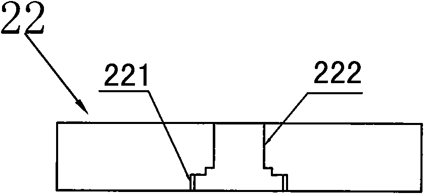
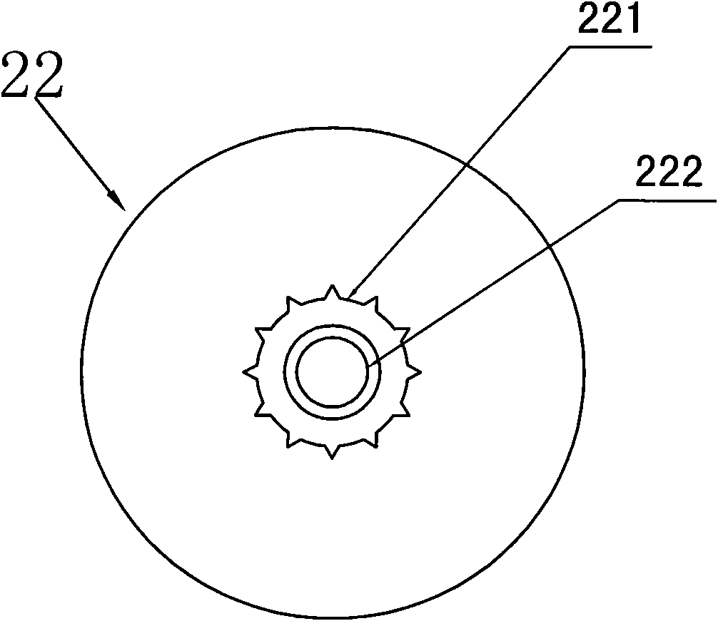
[0055] Such as figure 1 , 2 , 3, and 9, the artificial intervertebral discs 2 are respectively arranged at the upper and lower ends of the c...


PUM


Abstract

The invention relates to a novel cervical vertebra dynamic internal fixing device, which comprises an artificial cervical vertebra body and an artificial intervertebral disc. The artificial cervical vertebra body is inlaid on any vertebral body of the third section to the seventh section of partially cut human cervical vertebra. Two screw holes and two clamping grooves are symmetrically arranged on the artificial cervical vertebra body. A vertebral pedicle screw which is fixedly connected with the section of the human cervical vertebra body and a vertebral pedicle is arranged in each screw hole in a penetrating way. A vertebral pedicle screw lock pin cross bar is positioned and clamped between the two clamping grooves. The artificial intervertebral disc is arranged at the upper end and the lower end of the artificial cervical vertebra body, is arranged at a vertebral gap between an upper vertebral body and a lower vertebral body close to the position of the artificial cervical vertebra body, and comprises artificial nucleus pulposus and an artificial end plate. A screw hole is arranged on the artificial end plate. An artificial end plate fixing screw which is fixedly connected with the corresponding section of the artificial cervical vertebra body is arranged in the screw hole in a penetrating way. By adopting the internal fixing device, the invention has the advantages that the surgical invasion is small, the operation is easy and the dynamic fixation of the cervical vertebra after the subtotal excision of an anterior cervical single vertebral body can be realized.

Description

technical field [0001] The invention belongs to the technical field of clinical medicine and surgery, and relates to an orthopedic spinal internal fixation device capable of realizing dynamic fixation of the cervical spine at the surgical site after a single anterior cervical subtotal corpectomy, in particular, a new type of dynamic internal fixation device for the cervical spine . Background technique [0002] Mobility and stability of the cervical spine are two co-existing features of the human spinal structure. An ideal cervical spine internal fixation device should effectively preserve the physiological characteristics of the cervical spine while solving the patient's pain. This ideal intervertebral prosthesis should be able to restore the physiological mobility and stability of the surgical segment, and at the same time work effectively for a long time and have good durability. [0003] Up to now, at home and abroad, patients with cervical disc degenerative diseases w...

Claims


Application Information

Patent Timeline
Patent Type & Authority Applications(China)
IPC IPC(8): A61B17/70A61B17/86A61F2/44
CPCA61F2/44A61F2002/30001
Inventor 东人袁文
Owner 东人
Why Eureka
Try Eureka