

Catalyst for hydrogen generation through steam reforming of hydrocarbons
a hydrogen generation and catalyst technology, applied in the field of catalysts, can solve the problems of reducing catalyst activity, forming nickel oxide, and reforming catalyst exposed to cyclic operation conditions, and achieve the effect of retaining catalytic activity
- Summary
- Abstract
- Description
- Claims
- Application Information
AI Technical Summary
Benefits of technology
Problems solved by technology
Method used
Image

Examples
example 1
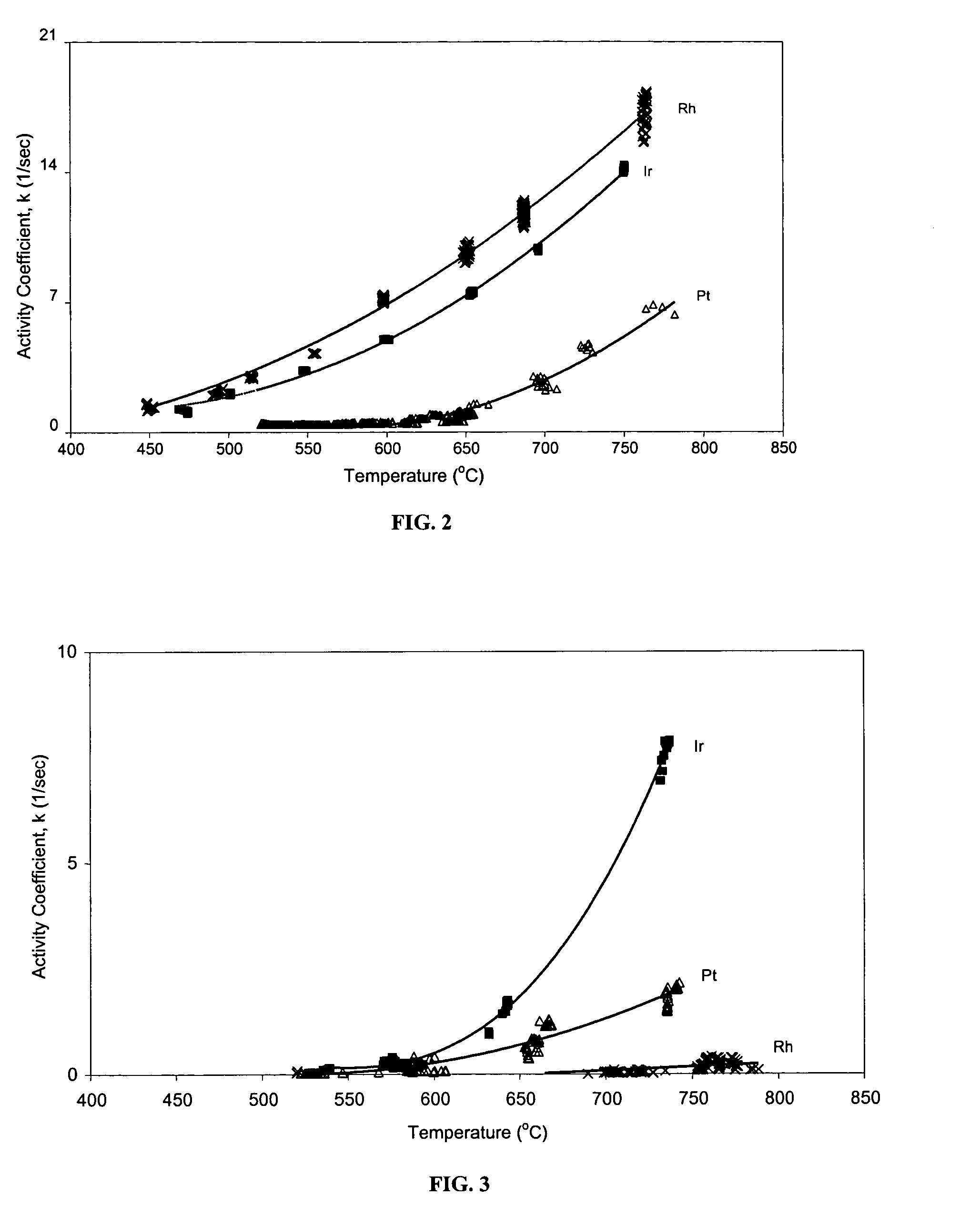
[0058] The activity of fresh catalysts containing Rh, Pt or Ir was compared with that of similar catalysts after aging.
[0059] Catalysts were prepared using a mixed calcium aluminate / alumina support loaded with 1 wt % Rh, Pt or Ir as active metal. The catalyst was synthesized by impregnating Rh, Pt, or Ir on a commercially available calcium aluminate / alumina support. The metals were deposited from an aqueous solution of the metal chloride or hexachloro-metal acid salt. After the supports were impregnated with the metal-containing solutions, the materials were dried at about 110° C. for 24 hours and then calcined in air at about 500° C.
[0060]FIG. 2 shows the variation of activity coefficient with temperature for each of the fresh catalysts in neat hydrocarbon feeds of methane with water added in a steam-to-carbon (methane) ratio of about 4:1. All three fresh catalysts demonstrate activity within the temperature range of about 600° C. to 800° C.
[0061]FIG. 3 shows the variation of ac...
example 2
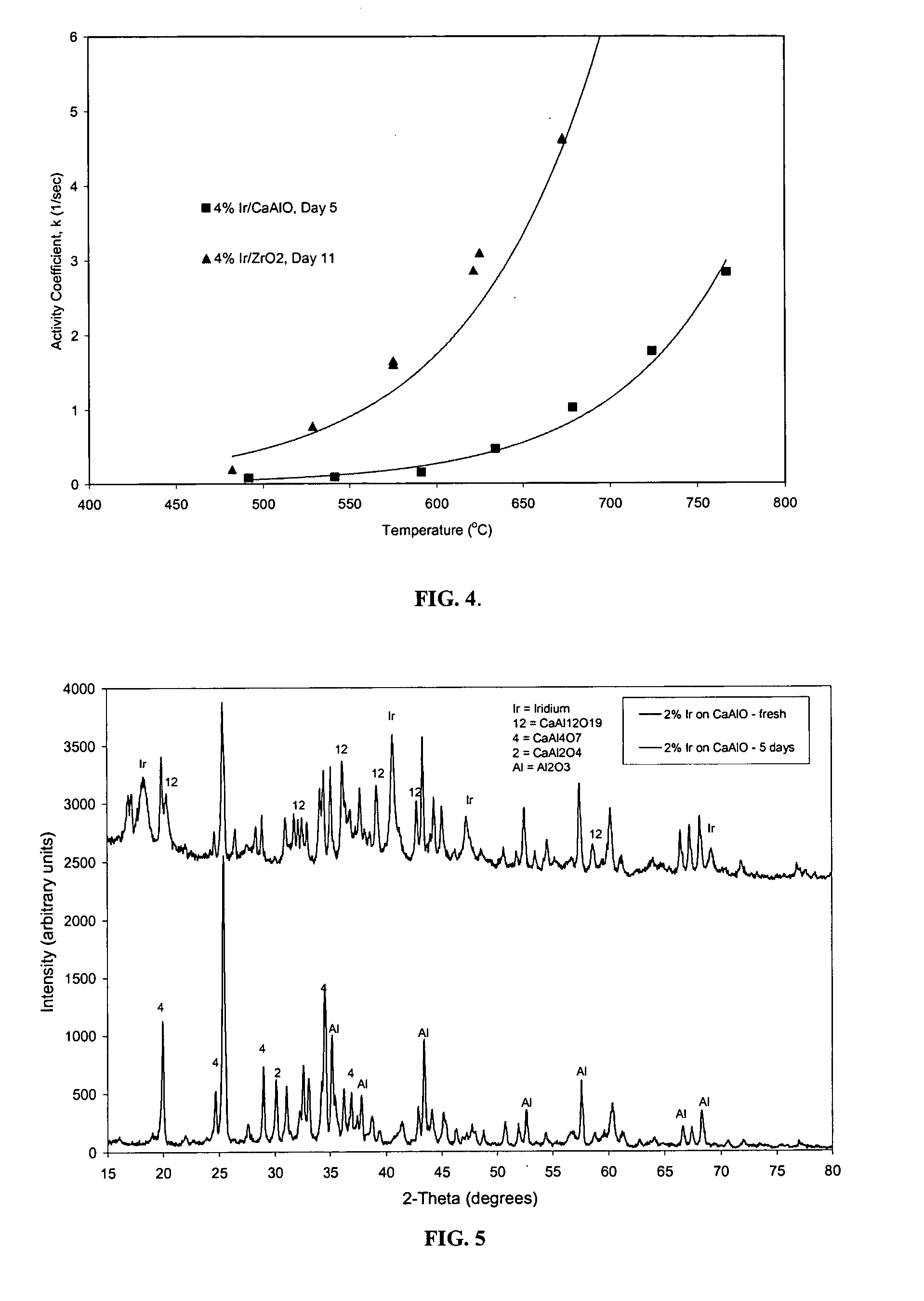
[0064] The activity of catalysts containing Ir on different catalyst supports was compared.
[0065] A catalyst was prepared by impregnating 4 wt % Ir on a mixed calcium aluminate / alumina support. The metal was deposited from an aqueous solution of hexachloroiridic acid. After the support was impregnated with the metal-containing solution, the catalyst was dried at about 110° C. for 24 hours and then calcined in air at about 500° C. The catalyst was aged for about 5 days on a hydrocarbon feed containing sulfur and oxygen, at a steam-to-carbon molar ratio of about 4, and at an average temperature of about 750° C.
[0066] A second catalyst was prepared by impregnating 4 wt % Ir on a pure monoclinic zirconia support. The metal was deposited from an aqueous solution of hexachloroiridic acid onto a commercially available monoclinic zirconia support. After the support was impregnated with the metal-containing solution, the catalyst was dried at about 110° C. for 24 hours and then calcined in...
example 3
[0068] The stability of different catalysts upon aging was studied.
[0069] A catalyst was prepared by impregnating 2 wt % Ir on a mixed calcium aluminate / alumina support. The metal was deposited from an aqueous solution of hexachloroiridic acid onto a commercially available calcium aluminate / aluminate support. After the support was impregnated with the metal-containing solution, the catalyst was dried at about 110° C. for 24 hours and then calcined in air at about 500° C.
[0070] A second catalyst was prepared by impregnating 2 wt % Ir on a monoclinic zirconia support. The metal was deposited from an aqueous solution of hexachloroiridic acid onto a commercially available monoclinic zirconia support. After the support was impregnated with the metal-containing solution, the catalyst was dried at about 110° C. for 24 hours and then calcined in air at about 500°.
[0071] Each catalyst was placed in a reactor and aged for five days at about 750° C. in the presence of sulfur-containing hydr...
PUM
| Property | Measurement | Unit |
|---|---|---|
| partial pressure | aaaaa | aaaaa |
| total pressure | aaaaa | aaaaa |
| partial pressure | aaaaa | aaaaa |
Abstract
Description
Claims
Application Information