Method for sealing gas drainage boreholes at specified positions

A technology for gas drainage and drainage pipes, which is applied in the direction of sealing/packing, drill pipes, drilling pipes, etc. It can solve the problem of jamming at the deformation of the baffle plate or veil, failure to feed the gas drainage pipe, and poor sealing effect To solve problems such as good or bad, to achieve the effect of prolonging the effective extraction period, convenient operation, and good sealing effect

Active Publication Date: 2010-09-29
CHINA UNIV OF MINING & TECH
View PDF7 Cites 27 Cited by
  • Summary
  • Abstract
  • Description
  • Claims
  • Application Information

AI Technical Summary

Problems solved by technology

Since the chemical slurry starts to react within a short time (40-60s) after mixing and stirring, the sealing depth can only reach 4-5m when the winding slurry method is used, and the sealing cannot be effectively avoided due to the loose ring of the roadway. poor hole quality
When the pressure injection grouting method is used to seal the hole, although the sealing depth can be increased, the cross section of the inner section of the gas drainage

Method used


Image

  • Method for sealing gas drainage boreholes at specified positions
  • Method for sealing gas drainage boreholes at specified positions
  • Method for sealing gas drainage boreholes at specified positions

Examples


Embodiment 1

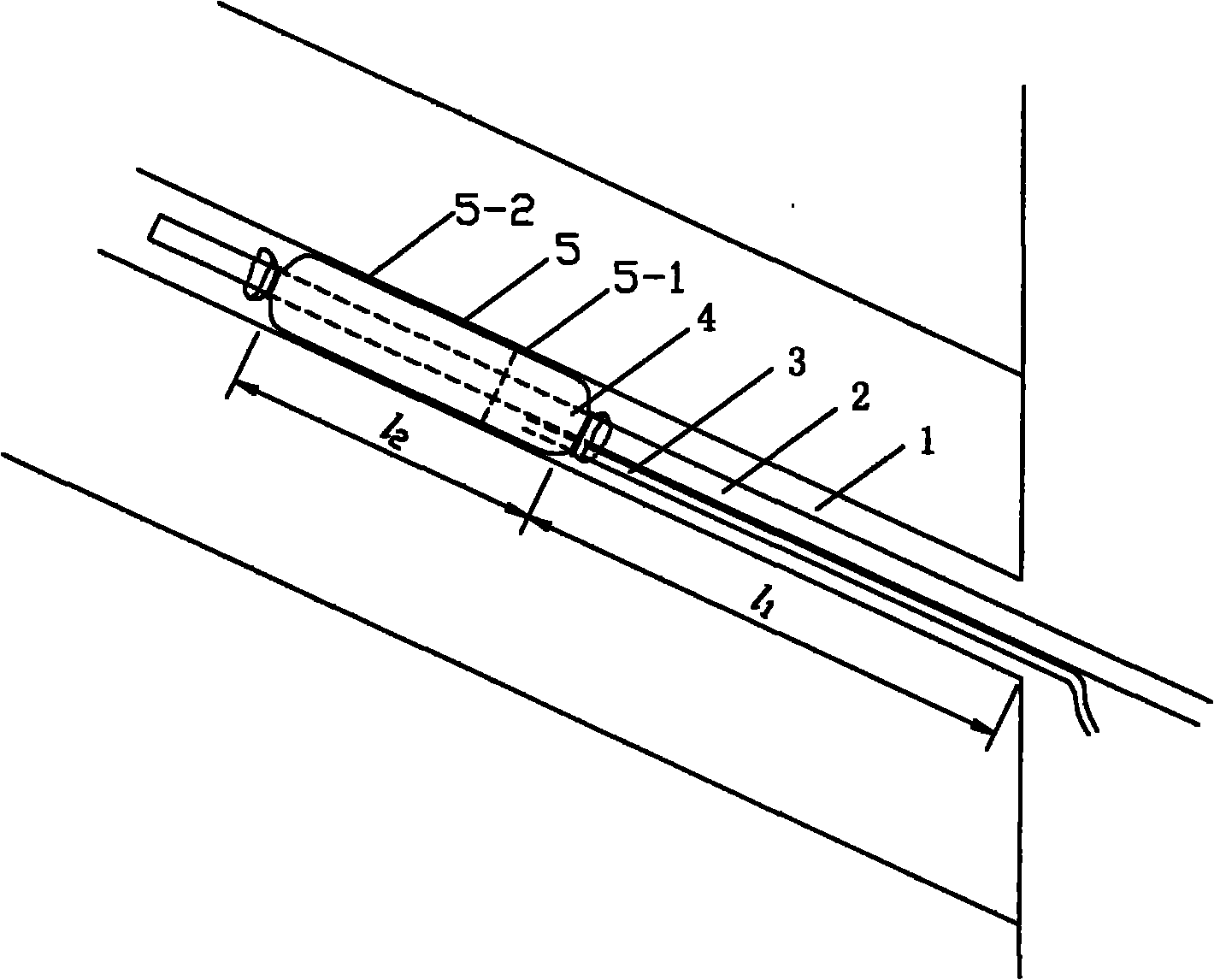
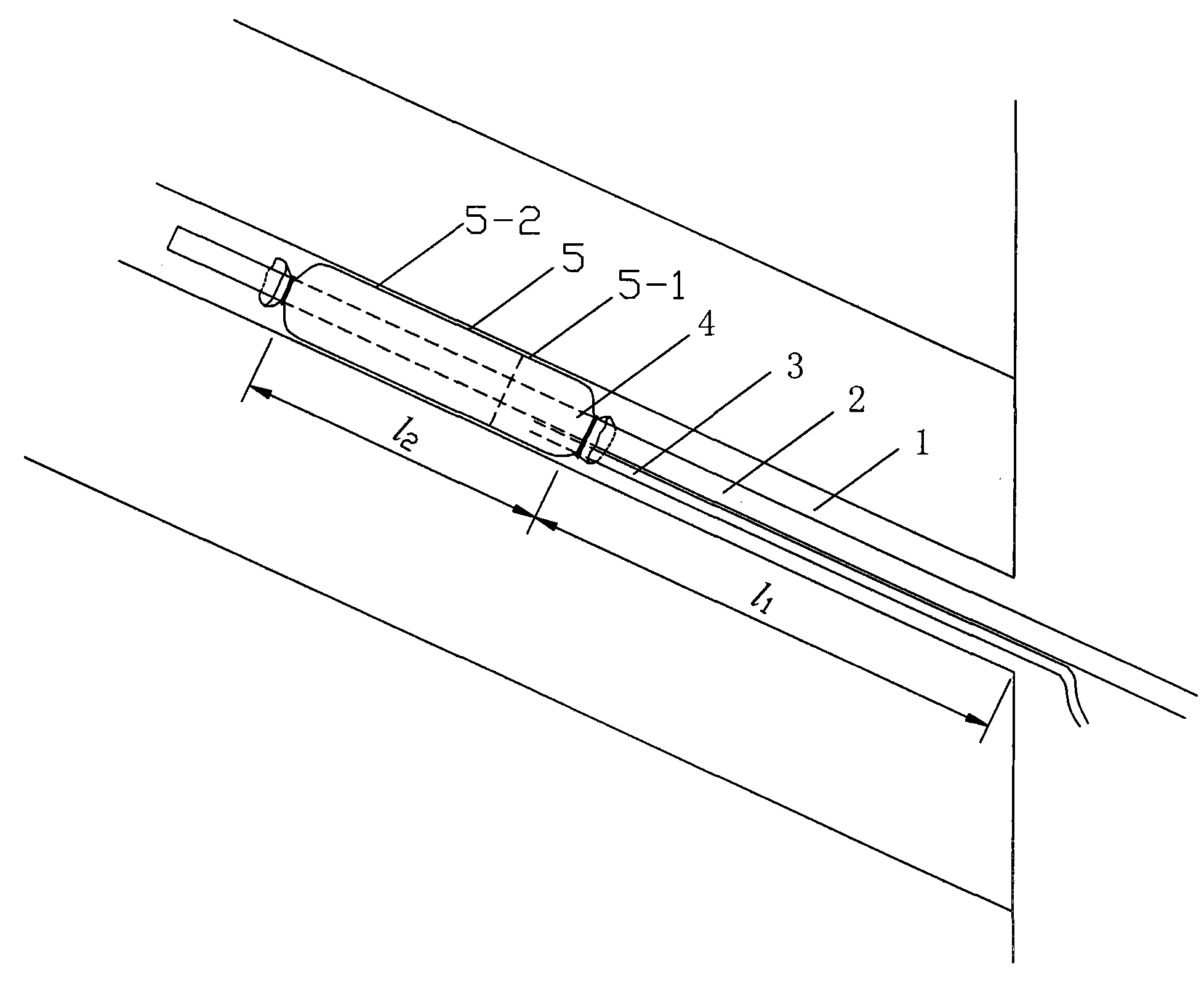
[0019] Embodiment one, figure 1 As shown, the method of sealing the ascending hole: the front part of the gas extraction pipe 2 to be inserted into the gas extraction hole 1 is covered with a cotton cuff section 5-2 and an antistatic tarpaulin cuff section 5-1. The total length l 2 The diameter of the flexible cuff 5 is larger than that of the gas drainage borehole 1, so that the sealing filling material 4 can contact the wall of the gas drainage borehole 1 after expanding. Cotton cuff section 5-2 faces inward, antistatic tarpaulin cuff section 5-1 faces outward, and the pore size of cotton cuff section 5-2 is 0.3-2 mm, allowing the liquid sealing filling material 4 to be placed on the cotton cloth A small amount of infiltration can be carried out when it flows upwards, which is beneficial to combine with the drainage hole wall; the length of the antistatic tarpaulin cuff section 5-1 is 0.3-1m to ensure that the slurry does not leak out. Insert the grouting tube 3 into the f...

Embodiment 2

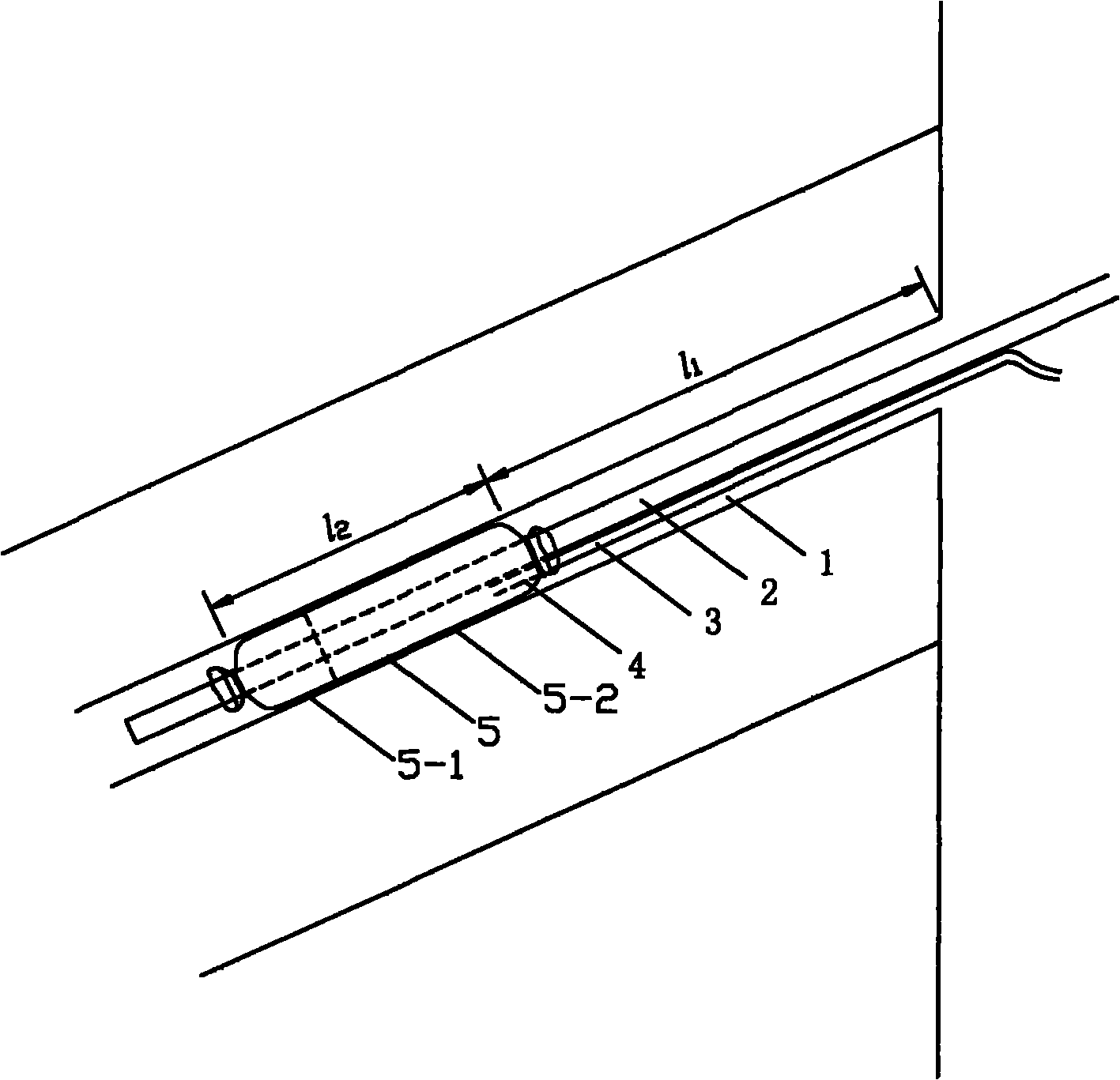
[0020] Embodiment two, figure 2 As shown, the method of sealing the down hole: since the angle direction of the sealing hole is downward, which is opposite to the angle direction of the upward sealing hole, the cotton cuff section 5-2 and the antistatic tarpaulin are set on the front part of the extraction pipe 2. The total length l of cuff segment 5-1 2 The flexible cuff 5 of 2~4m is also opposite, promptly the cotton cuff section 5-2 outwards, the waterproof cloth cuff section 5-1 section of antistatic is inward, and other is all identical with embodiment one, identical part is omitted.


PUM

PropertyMeasurementUnit
Sizeaaaaaaaaaa
Lengthaaaaaaaaaa
Lengthaaaaaaaaaa

Abstract

The invention relates to a method for sealing gas drainage boreholes at specified positions, which comprises a drainage tube, an injection tube and a flexible sleeve, the flexible sleeve is sleeved on the front part of the drainage tube, the injection tube is inserted into the flexible sleeve, and both ends of the flexible sleeve are then tightly bound on the drainage tube; the drainage tube and the injection tube are put into the specified position of a gas drainage borehole together, the injection tube injects sealing filling material into the hermetic flexible sleeve until the flexible sleeve is filled up with the sealing filling material, and after the filling material is expanded, the borehole is sealed. The distance between the outer end of the flexible sleeve and the orifice of theborehole is larger than 8m, and the length of the flexible sleeve is larger than 2m; the flexible sleeve consists of a cotton cloth sleeve section and an antistatic waterproof cloth sleeve section, and the waterproof cloth of the flexible sleeve is used for preventing the seepage of the sealing filling material; and the diameter of the flexible sleeve is larger than the diameter of the gas drainage borehole, so that the radially expanded sealing filling material can be tightly combined with the wall of the borehole. The method has the advantages of good borehole sealing effect, high drained gas concentration, long effective drainage time and simple and quick operation.

Description

technical field [0001] The invention relates to a fixed-point sealing gas drainage borehole method, which is suitable for precisely controlling the sealing depth and sealing position, increasing the sealing depth of the gas drainage borehole, and improving the gas drainage effect. Background technique [0002] Gas is one of the five natural disasters in coal mines, which seriously threatens the safety of mines. In order to prevent and control gas disasters and ensure safe production in mines, mining coal seam or goaf gas by construction drilling is an effective measure to reduce the gas content in coal seam and gas emission in working face. The gas drainage rate of coal mines in my country is generally low. In addition to the influence of geological conditions such as low coal seam permeability coefficient, the main reason is that the quality of drilling hole sealing is poor, resulting in serious gas leakage and low concentration of gas drainage. [0003] At present, my cou...

Claims


Application Information

Patent Timeline
IPC IPC(8): E21B33/13E21B17/00
Inventor 周福宝胡东亮刘应科张云峰胡胜勇
Owner CHINA UNIV OF MINING & TECH
Why Eureka
Try Eureka