

Transition gear and transition gear train
A technology of gear trains and gears, which is applied in the field of transition gears and transition gear trains, can solve the problems that the piston cannot be reciprocated and cannot be used as an internal combustion engine power conversion mechanism, etc., so as to alleviate the energy shortage, reduce the volume of the combustion chamber, and improve environmental protection. Effect
- Summary
- Abstract
- Description
- Claims
- Application Information
AI Technical Summary
Problems solved by technology
Method used
Image

Examples
Embodiment Construction
[0063] 1. Implementation mode of transition gear:
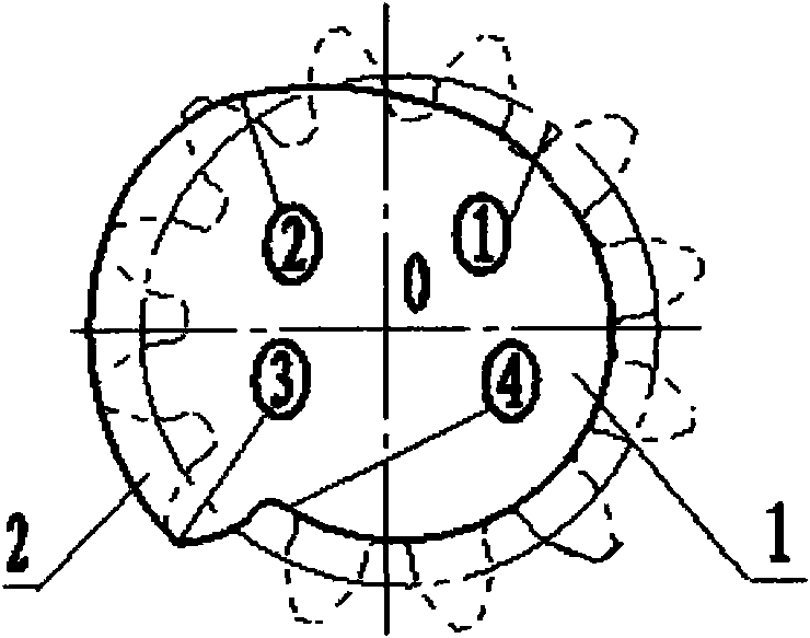
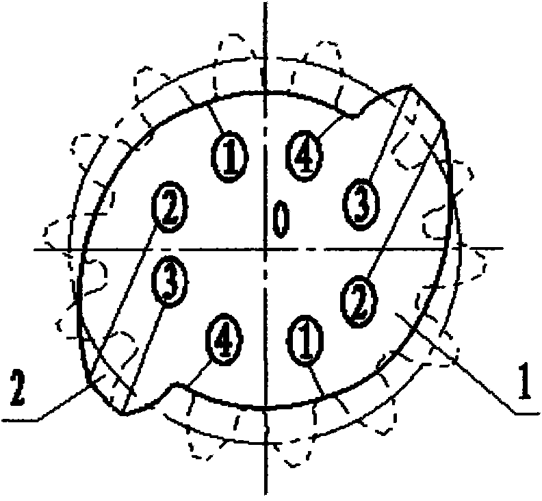
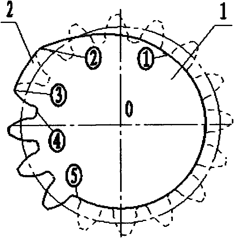
[0064] The transitional gear is deformed based on the tooth profile data of the usual gear pair as an example. Such as figure 1 , figure 2 , image 3 The dotted line in is the involute tooth profile of the unused parallel shaft gear pair, the toothless part ⑤-① or ④-① is the dedendum arc of the normal gear, and the normal tooth part ⑤-④ is the involute tooth profile , but the tooth height can be raised and lowered, and the tooth width increased (such as Figure 5 The tooth rack of the transition section ③-④ is an involute tooth profile, but the shape of the tooth profile can be changed according to the needs; the transition middle section ②-③ tooth profile is the tooth top of the involute gear, but it can be as follows figure 1 , Figure 4 Change the height and shape of part of the addendum in that way, and push the rack to continue to move forward to reach the end of the stroke; the transitional front section ①-② is th...
PUM
 Abstract
Description
Claims
Application Information